Reconfigurable leak testing system

A leak test and structure technology, applied in the field of automatic leak test systems for auto parts, can solve problems such as wasting time and reduce costs

Active Publication Date: 2014-03-26
GM GLOBAL TECH OPERATIONS LLC
View PDF6 Cites 5 Cited by
  • Summary
  • Abstract
  • Description
  • Claims
  • Application Information

AI Technical Summary

Problems solved by technology

Often, leak testing machines must be set up to fit specific parts, and time is wasted during such a process

Method used


Image

  • Reconfigurable leak testing system
  • Reconfigurable leak testing system
  • Reconfigurable leak testing system

Examples


Embodiment Construction

[0069] The following description is merely exemplary in nature and is not intended to limit the disclosure, application or uses.

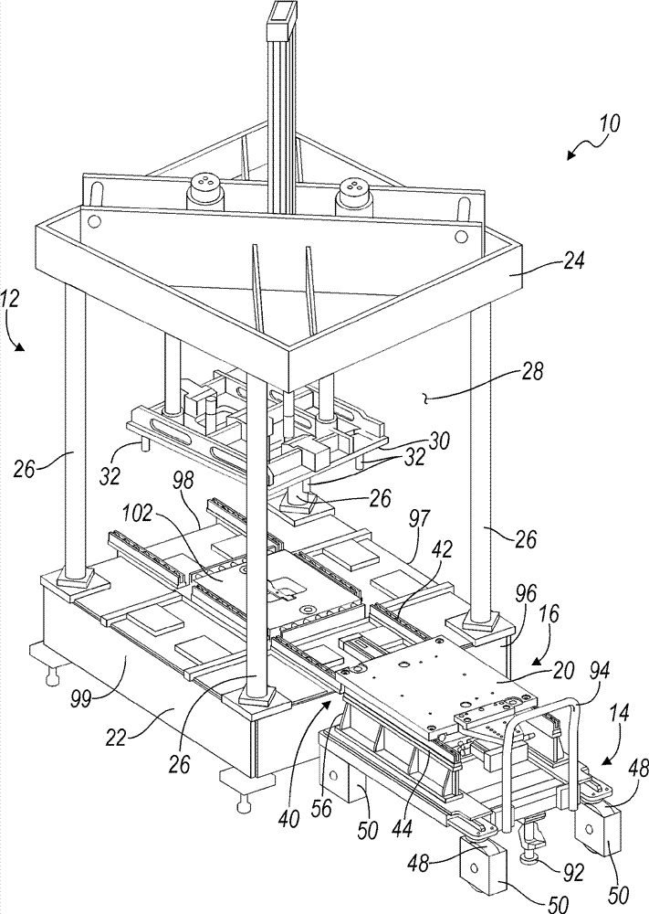
[0070] Referring to the drawings, in which like reference numerals are used to identify like or identical parts throughout the several views, Figure 1 to Figure 2A reconfigurable leak testing system 10 including a leak testing workstation 12 , a transfer shuttle 14 and one or more leak testing fixture decks 16 is shown. Each clamp receptacle 16 may include a respective upper clamp 18 and lower clamp 20 . In addition, each clamp bay 16 is independently translatable along the transfer shuttle 14, as will be further described below.

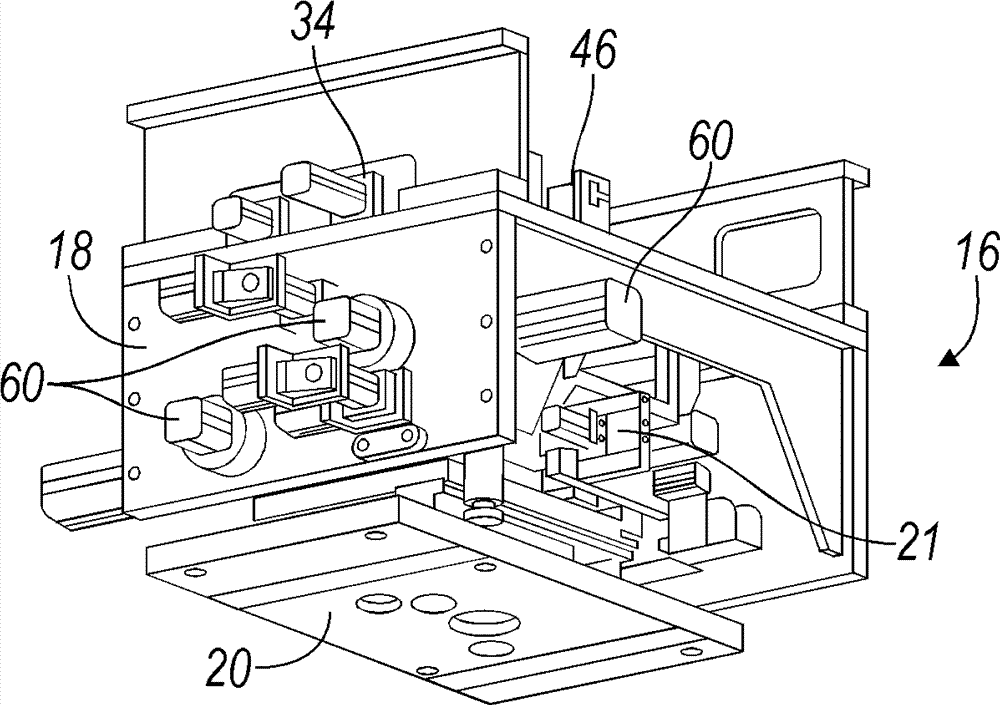
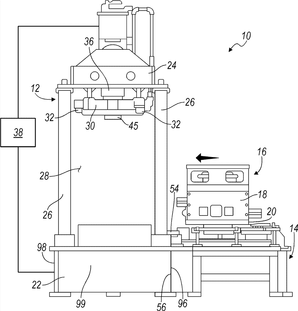
[0071] image 3 The leak testing system 10 is also shown, but only the lower clamp 20 of the clamp deck 16 is shown so as not to block the view of further details of the leak testing system 10 . Figure 4 The entire clip holder 16 is shown with the part 21 disposed therein. Such as figure 2 As shown, once jig deck...


PUM


Abstract

A reconfigurable leak testing system is provided that includes a leak testing station and at least one off-shuttle cart removably attachable to the leak testing station. A fixture cartridge is translatable between the off-shuttle cart and the leak testing station. The fixture cartridge is configured to selectively couple with the leak testing station. The fixture cartridge includes an upper fixture, a lower fixture, and an actuatable testing feature. The fixture cartridge is configured to receive a part between the upper fixture and lower fixture. The actuatable testing feature is configured to contact the part. A closed volume is defined at least partially by the actuatable testing feature and the part.

Description

[0001] Cross References to Related Applications [0002] This application is a continuation-in-part of US Patent Application No. 13 / 195,517, filed August 1, 2011, which is incorporated herein by reference in its entirety. technical field [0003] The present invention relates to leak testing systems for automotive parts, and in particular to automated leak testing systems and methods for automotive parts. Background technique [0004] The statements in this section merely provide background information related to the present disclosure and may or may not constitute prior art. [0005] Casting is a metal forming technique that involves pouring molten metal into a hollow cavity in a mold, where the cavity is the negative of the desired part shape. As the molten metal cools in the cavity, the metal hardens and can then be separated from the mold as a solid part. Casting processes can be used to form relatively complex metal parts that would otherwise be uneconomical to manufa...

Claims


Application Information

Patent Timeline
Patent Type & Authority Applications(China)
IPC IPC(8): G01M3/02
CPCG01M3/025G01M3/329
Inventor S.南德瓦尼B.霍尔姆斯C.A.布莱克
Owner GM GLOBAL TECH OPERATIONS LLC
Why Eureka
Try Eureka