Method and system for controlling local color gamut, backlight source and display device

A backlight and color gamut technology, applied to static indicators, cathode ray tube indicators, instruments, etc., can solve the problems of energy waste, inability to reduce backlight power consumption, high energy consumption, etc.

Active Publication Date: 2014-03-26
HEFEI BOE OPTOELECTRONICS TECH +1
View PDF4 Cites 20 Cited by
  • Summary
  • Abstract
  • Description
  • Claims
  • Application Information

AI Technical Summary

Problems solved by technology

For liquid crystal display devices, the color gamut is determined by the color filter and the backlight. In the case of the same color filter, different color gamut requirements can be achieved by replacing the backlight, but the brightness of the backlight and the display The ability of the color gamut is inversely proportional to the relationship, so when a certain brightness is satisfied, a high color gamut display requires relatively high backlight power consumption; similarly, when the backlight remains unchanged, different color gamuts require different In order to achieve a high color gamut, a high-filtering color filter is required, but a high-filtering color filter will cause the light transmittance of the LCD panel to decrease, and it must be increased in order to ensure normal display. The power consumption of the backlight, so when displaying a high color gamut picture, a relatively high power consumption of the backlight is required
[0003] High color gamut display is the common goal of current

Method used


Image

  • Method and system for controlling local color gamut, backlight source and display device
  • Method and system for controlling local color gamut, backlight source and display device
  • Method and system for controlling local color gamut, backlight source and display device

Examples


Embodiment 1

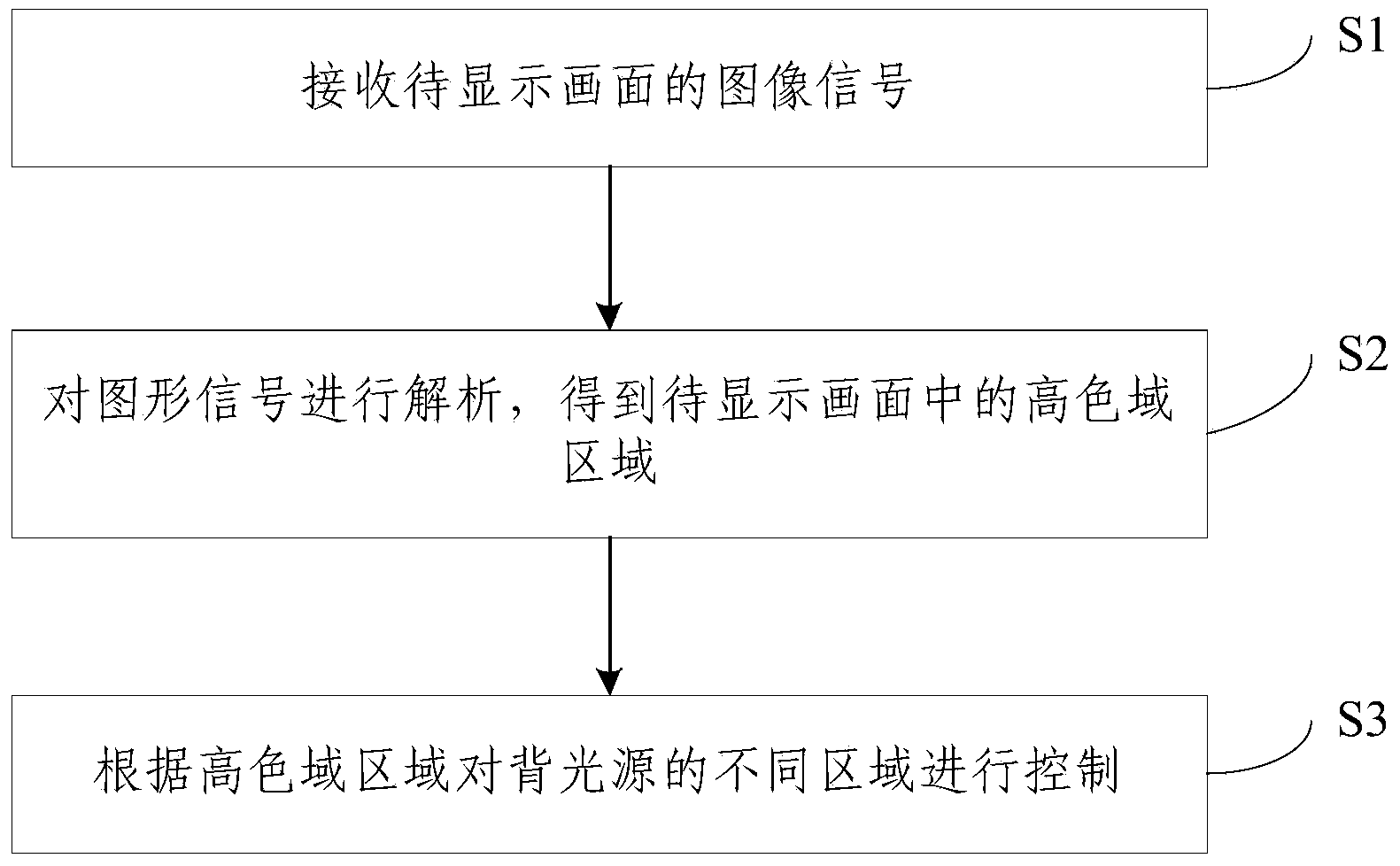
[0044] Embodiment 1 of the present invention provides a method for controlling a local color gamut, the method flow chart is as follows figure 2 As shown, it specifically includes the following steps:

[0045] Step S1. Receive an image signal of a picture to be displayed.

[0046] Step S2, analyzing the graphic signal to obtain a high color gamut area in the image to be displayed, wherein the high color gamut area is an area whose color gamut value exceeds a preset range.

[0047] Step S3, controlling different areas of the backlight source according to the high color gamut area.

[0048] This method analyzes the image signal to be displayed, divides it into high color gamut area and low color gamut area according to the color gamut value, and realizes the control of different areas of the backlight according to the high color gamut area obtained from the analysis result, realizing In some areas that do not need to display high color gamut images, it is only necessary to turn...

Embodiment 2

[0063] Embodiment 2 of the present invention also provides a system for controlling local color gamut, the composition diagram is as follows Figure 5 shown, including:

[0064] An image receiving device 10, a first image analyzing device 20 and a first control device 30, wherein the image receiving device 10 is used to receive an image signal of a picture to be displayed;

[0065] The first image analysis device 20 is configured to analyze the graphic signal to obtain a high color gamut area in the picture to be displayed, wherein the high color gamut area is an area whose color gamut value exceeds a preset range;

[0066] The first control device 30 is used for controlling different areas of the backlight source according to the high color gamut area.

[0067] The image receiving device of the above system receives the image signal of the image to be displayed, and is analyzed by the first image analysis device to obtain the high color gamut, and then the first control devi...

Embodiment 3

[0075] Embodiment 3 of the present invention provides a backlight, wherein the LED array of the backlight includes at least one partial array unit, and the LEDs in each partial array unit are controlled on and off by a circuit.

[0076] In this embodiment, the entire backlight source is divided into multiple local array units, and circuit control is performed on the LED lamps in each local array unit to turn on and off, so as to display high color gamut in some local array areas according to the screen display requirements. , and the remaining local array area displays a low color gamut area, which can not only ensure high-quality display images, but also reduce unnecessary power consumption and achieve the purpose of energy saving.

[0077] Preferably, each divided partial array unit includes high color rendering LED lamps and low color rendering LED lamps, and the on and off states of the high color rendering LED lamps and low color rendering LED lamps are individually contro...


PUM


Abstract

The invention discloses a method and a system for controlling a local color gamut, a backlight source and a display device. The method comprises the steps of receiving an image signal of a frame to be displayed; resolving the image signal to obtain a high-color-gamut region in the frame to be displayed, wherein a color-gamut value of the high-color-gamut region exceeds a preset range; controlling different regions of the backlight source according to the high-color-gamut region. In the method, the image signal to be displayed is analyzed and divided into a high-color-gamut region and a low-color-gamut region according to the color-gamut value, the high-color-gamut region is obtained according to an analysis result, control of different regions of the backlight source is achieved, and only a low-color-rendering LED lamp is required to be lightened on in several regions in which high-color-gamut images are not required to be displayed. Therefore, the power consumption of the backlight source can be reduced while the frame quality is ensured, and the energy-saving purpose is achieved. The invention further provides the system for controlling the local color gamut based on the method, the backlight source and the display device including the backlight source. Energy saving is achieved.

Description

technical field [0001] The invention relates to the field of display technology, in particular to a method, a system, a backlight source and a display device for controlling a local color gamut. Background technique [0002] In the field of display, for various display devices, printers and printing devices, the commonly used color gamut represents the range of color types that a certain device can express. The colors that can be displayed in nature that are visible to the human eye constitute the largest color gamut space. If The larger the color gamut of a certain device, the richer the colors it can represent, that is, the stronger the ability to display natural colors. For liquid crystal display devices, the color gamut is determined by the color filter and the backlight. In the case of the same color filter, different color gamut requirements can be achieved by replacing the backlight, but the brightness of the backlight and the display The ability of the color gamut i...

Claims


Application Information

Patent Timeline
IPC IPC(8): G09G3/34G09G3/36G09G5/02
Inventor 王欢辛武根吕昶占江徽
Owner HEFEI BOE OPTOELECTRONICS TECH
Why Eureka
Try Eureka