Quick vacuum circuit breaker

A vacuum circuit breaker, fast technology, applied in the direction of high-voltage air circuit breakers, circuits, electrical components, etc., can solve the problems of high cost, bulky, poor reliability, etc., achieve fast action speed, improve operation reliability, and high reliability Effect

Inactive Publication Date: 2014-03-26
STATE GRID CORP OF CHINA +1
View PDF10 Cites 6 Cited by
  • Summary
  • Abstract
  • Description
  • Claims
  • Application Information

AI Technical Summary

Problems solved by technology

Therefore, conventional series capacitor devices inevitably have the problems of bulky, expensive, technically complex, and poor reliability,

Method used


Image

  • Quick vacuum circuit breaker

Examples


Embodiment Construction

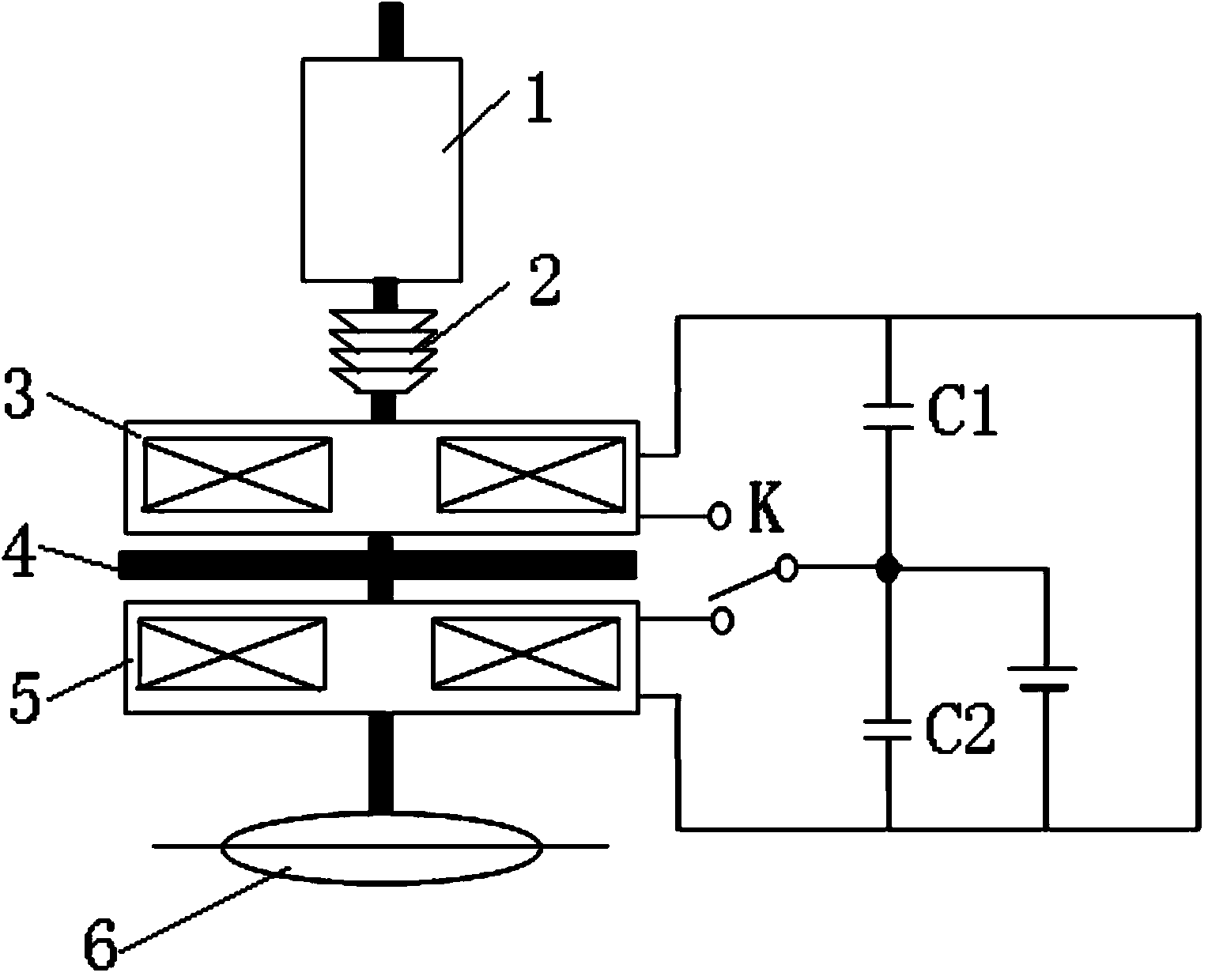
[0012] Such as figure 1 As shown, the present invention is a fast vacuum circuit breaker, including a vacuum interrupter 1, a moving contact is installed in the vacuum interrupter 1, the moving contact is connected with a moving conductive rod and the end of the moving conductive rod Extending out of the vacuum interrupter 1, the end of the moving conductive rod is connected to one end of the insulator 2, and the other end of the insulator 2 is connected to one side of the opening coil 3 through a connecting rod, and the other end of the opening coil 3 One side is connected to one side of the closing coil 5 through a connecting rod, the other side of the closing coil 5 is connected to the disc spring through a connecting rod, and the connecting rod between the aforementioned opening coil 3 and the closing coil 5 Also be equipped with swirl disk 4 on.

[0013] Such as figure 1 As shown, the second terminal of the opening coil 3 and the second terminal of the closing coil 5 ar...


PUM


Abstract

The invention relates to a quick vacuum circuit breaker. The quick vacuum circuit breaker is characterized in that the tail end of a movable conducting rod is connected with one end of an insulator (2), the other end of the insulator (2) is connected with one side of an opening coil (3) by a connecting rod, the other side of the opening coil (3) is connected with one side of a closing coil (5) by a connecting rod, the other end of the closing coil (5) is connected with a disc spring by a connecting rod, and an eddy current disc (4) is further mounted on the connecting rod between the opening coil (3) and the closing coil (5); a second wiring terminal of the opening coil (3) and a second wiring terminal of the closing coil (5) are respectively connected with two output ends of a selector control switch (K), and the quick vacuum circuit breaker further comprises a first energy storage capacitor (C1) and a second energy storage capacitor (C2) which are serially connected with each other. The quick vacuum circuit breaker has the advantages that the closing time can be about 12ms, and the opening time can be within a range of 5ms under the control.

Description

technical field [0001] The invention relates to a fast vacuum circuit breaker. Background technique [0002] The method of using series capacitors to offset the line inductive reactance to solve the voltage quality problem at the end of the line has been applied in China as early as the 1960s. With the maturity of controllable gap and power electronics technology, series compensation devices for high voltage and ultra-high voltage have also been put into operation in recent years. During normal operation, only working current flows in the line, and the voltage at both ends of the series capacitor device is close to about 1 / 10 of the working voltage of the line. But this does not mean that it is allowed to select the series capacitor according to 1 / 10 of the line operating voltage, because when the line is short-circuited, the voltage across the series capacitor will be ten times or even dozens of times higher than normal, which requires The series capacitor device must be ...

Claims


Application Information

Patent Timeline
IPC IPC(8): H01H33/66H01H33/666
Inventor 艾绍贵李延军宋永强罗强梁俊栗树华王明黄永宁李俊马奎张爽吴良方
Owner STATE GRID CORP OF CHINA
Why Eureka
Try Eureka