Multi-directional pay-off block

A technology of pay-off pulley and side plate, applied in the direction of overhead lines/cable equipment, etc., can solve the problems of increasing the workload of construction personnel, affecting the safe and stable operation of the power system, and heating of contacts, so as to avoid wire jamming or damage to the insulation layer of wires , reduce potential safety hazards, and avoid disconnection effects

Active Publication Date: 2016-04-06
STATE GRID CORP OF CHINA +2
View PDF8 Cites 0 Cited by
  • Summary
  • Abstract
  • Description
  • Claims
  • Application Information

AI Technical Summary

Problems solved by technology

This way of laying out wires not only increases the workload of the construction personnel, but also the contacts at the corners are exposed to the outside for a long time, and the contacts will heat up, which seriously affects the safe and stable operation of the power system.

Method used


Image

  • Multi-directional pay-off block
  • Multi-directional pay-off block

Examples


Embodiment Construction

[0022] Below in conjunction with accompanying drawing and specific embodiment the present invention is described in further detail:

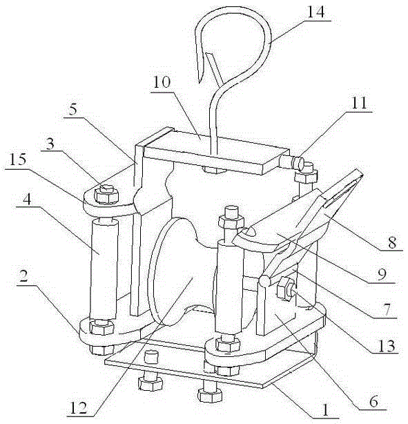
[0023] Multi-directional pay-off block, its structure is as follows figure 1 Shown, comprise base 1, support, roller 12 and nylon steering bar 4.

[0024] The base 1 is a U-shaped structure placed horizontally, and the lower bottom plate of the base 1 is provided with matching bolt holes and bolts for fixing the base 1 on a pole tower or a cross arm.

[0025] The support includes a lower fixing plate 2, a beam 10 and two side plates. In this embodiment, the lower fixing plate adopts a strip structure, and there are two pieces in total. The two lower fixing plates 2 are welded side by side on the top plate of the base 1. Both ends of the lower fixing plate 2 are provided with bolt holes. Four iron pins 3 Bolt holes are respectively vertically arranged at the two ends of the two lower fixing plates 2, both ends of the iron pin 3 are provided wit...


PUM


Abstract

The invention discloses a multi-directional paying-off tackle applicable to the technical field of electric mounting. The tackle comprises a support and a roller disposed on the support through a roller shaft. The support comprises a lower fixing plate, a first side plate and a second side plate, wherein the first side plate and the second side plate are vertically disposed on two sides of the lower fixing plate, the top ends of the first side plate and the second side plate are connected through a crossbeam, the roller shaft vertical to the two side plates are disposed between the middles of the two side plates, two sides, located on the side plates, of the lower fixing plate are symmetrically provided with four iron pins, a nylon turning bar is sleeved on each iron pin, the second side plate includes a support plate fixed on the lower fixing plate and a movable plate capable of being opened and closed, and a locking mechanism for locking the movable plate is disposed on the outer side of the same. The multi-directional paying-off tackle has the advantages that the tackle is capable of smoothly paying-off in corner paying-off paths, procedures such as wire breaking and connecting can be avoided, work load of operators is reduced, wire connecting points are reduced, potential safety hazard is reduced, and safety performance of an electric system is increased.

Description

technical field [0001] The invention relates to a power installation device, in particular to a pay-off tackle. Background technique [0002] The pay-off block is widely used in the power industry for laying pipelines, which can improve work efficiency and reduce pipeline damage. The traditional pay-off block includes rollers, which are set on the bracket through the pin shaft. When in use, the pay-off block is first suspended in the air or placed on the ground, and secondly, the wire is placed on the roller, and then the free end of the wire is pulled and moved toward Apply force in front, so that the pulley rotates to achieve the purpose of releasing the line. However, in the construction process, due to the complex terrain, there are often many corners in the pay-off path. When using the traditional pay-off block, the line jam problem often occurs, that is, the wire is stuck in the gap between the edge of the roller and the bracket, especially at the corner. Especially ...

Claims


Application Information

Patent Timeline
Patent Type & Authority Patents(China)
IPC IPC(8): H02G1/02
Inventor 刘占雄申丙岐郭沛然王敏鑫
Owner STATE GRID CORP OF CHINA
Why Eureka
Try Eureka