Relay protection method for dead-zone faults of voltage transformers on basis of starting at switching positions and sealed current transformers TA

A relay protection, switch position technology, applied in emergency protection circuit devices, electrical components, etc., can solve the problems of failure to reach the starting value, long time to remove faults, etc., to increase the T time loop, the criterion is simple and practical, The effect of enhancing security

Inactive Publication Date: 2014-03-26
STATE GRID CORP OF CHINA +3
View PDF5 Cites 3 Cited by
  • Summary
  • Abstract
  • Description
  • Claims
  • Application Information

AI Technical Summary

Problems solved by technology

Since the fault is outside the protection range of the transformer longitudinal differential protection, although the backup protection or other protection (such as busbar protection) on the fault side operates to trip the circuit breaker on the side of the transformer, the fault still exists. The protection action or the backup protection action of this side is used to trip the general outlet circuit of the transformer and trip the circuit breaker on the power

Method used


Image

  • Relay protection method for dead-zone faults of voltage transformers on basis of starting at switching positions and sealed current transformers TA
  • Relay protection method for dead-zone faults of voltage transformers on basis of starting at switching positions and sealed current transformers TA

Examples


Embodiment Construction

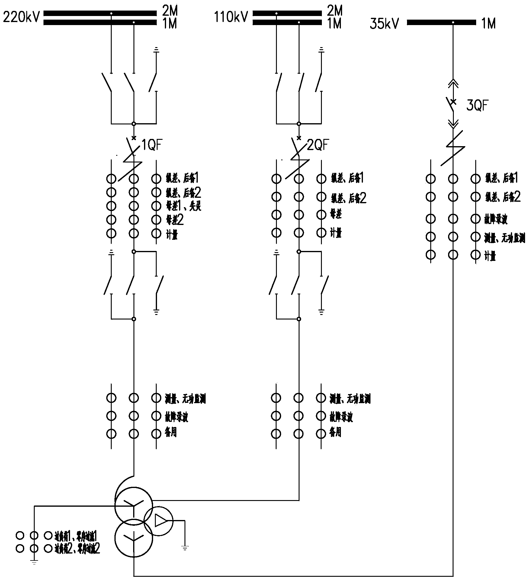
[0029] Taking the protection of a 220kV autotransformer in a 220kV substation as an example, to describe the method of quickly starting and removing the fault in the dead zone of the transformer, the transformers of other voltage levels, and the transformers are two-winding transformers, three-winding For other transformers, or combinations of other voltage levels on each side of the transformer, the methods are similar and will not be repeated here. Such as figure 2 As shown, it is part of the primary main wiring diagram of a 220kV substation, a 220kV autotransformer, the transformer is equipped with a high-voltage side circuit breaker 1QF, a medium-voltage side circuit breaker 2QF, and a low-voltage side circuit breaker 3QF; the high-voltage side circuit breaker 1QF A set of independent TAs are installed at 2QF of the circuit breaker on the medium voltage side and 3QF of the circuit breaker on the low voltage side. TAs have several sets of secondary windings respectively. T...


PUM


Abstract

The invention relates to a relay protection method for dead-zone faults of voltage transformers on the basis of starting at switching positions and sealed current transformers TA. The relay protection method includes setting four conditions during tripping control for the dead-zone faults on certain sides of the voltage transformers; enabling the differential protection current transformers TA on the certain sides of the voltage transformers to withdraw after time delay elapses if the conditions are met; accessing the transformer differential protection current transformers TA on the sides of the voltage transformers after the time of 0s elapses if an optional condition is not met. The first condition includes that local-side backup protection current elements for removing side circuit breakers of the voltage transformers are started; the second condition includes that the side circuit breakers of the voltage transformers are located at opening positions; the third condition includes that primary pulse T-time opening protection is started if the first condition and the second condition are met; the fourth condition includes that A-phase or B-phase or C-phase currents of the certain sides of the voltage transformers reach starting values or zero-sequence currents Io or negative-sequence currents I2 reach starting values. The relay protection method has the advantages of simple action principle, high reliability and capability of quickly removing the various voltage grades of dead-zone faults of various sides of the voltage transformers.

Description

technical field [0001] The invention belongs to the control technology of electric power transmission and distribution network, and relates to a transformer dead zone fault relay protection method based on switch position starting and closing TA. Background technique [0002] GB / T14285-2006 "Technical Regulations for Relay Protection and Safety Automatic Devices" stipulates that the transformer should be equipped with longitudinal differential protection as the main protection and electrical protection such as backup protection for transformer overcurrent caused by external phase-to-phase short circuit and grounding short circuit, Among them, the backup protection for responding to phase-to-phase short circuit includes composite voltage overcurrent protection and phase-to-phase impedance protection, and the backup protection for responding to grounding short circuit includes zero-sequence current protection and grounding impedance protection. These backup protections are equ...

Claims


Application Information

Patent Timeline
IPC IPC(8): H02H7/045
Inventor 汤大海侯喆龙峰曹斌
Owner STATE GRID CORP OF CHINA
Why Eureka
Try Eureka