
Stator of rotary motor

A technology for rotating electrical machines and stators, which is applied in the manufacture of motor generators, electrical components, electromechanical devices, etc. It can solve problems such as loosening, deformation of the inner and outer diameters of stator cores, and adverse effects on motor performance, so as to improve material utilization and production efficiency , Conducive to the control of dimensional accuracy or positional accuracy

Inactive Publication Date: 2014-03-26
SHANGHAI MITSUBISHI ELEVATOR CO LTD
View PDF11 Cites 8 Cited by
  • Summary
  • Abstract
  • Description
  • Claims
  • Application Information

AI Technical Summary

Problems solved by technology

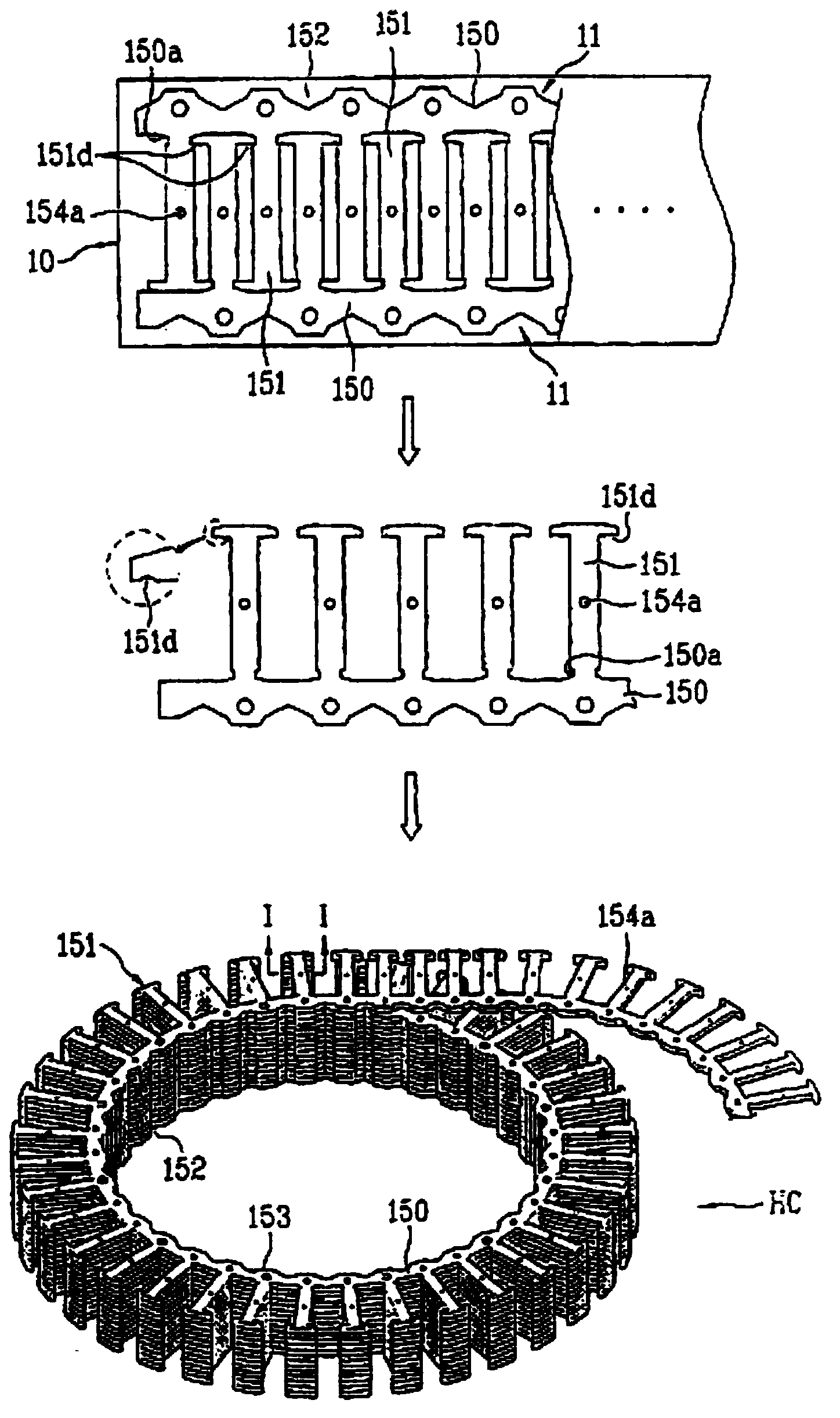
Although this manufacturing method can reduce the number of assembly processes and improve manufacturing efficiency, it is not difficult to imagine that the first magnetic pole tooth engagement part and the second magnetic pole tooth joint part are easy to fit in the mutual fitting process due to the small area of ​​the fitting part. If the fit is not tight enough to cause loosening, or if the fit is too tight to cause stress deformation, it is also easy to interfere with each other at the fit due to poor control of the dimensional accuracy or position accuracy of the fit, and the inner and outer diameters of the stator core will be deformed, which will adversely affect the performance of the motor.

Method used


Image

  • Stator of rotary motor
  • Stator of rotary motor
  • Stator of rotary motor

Examples


no. 1 example

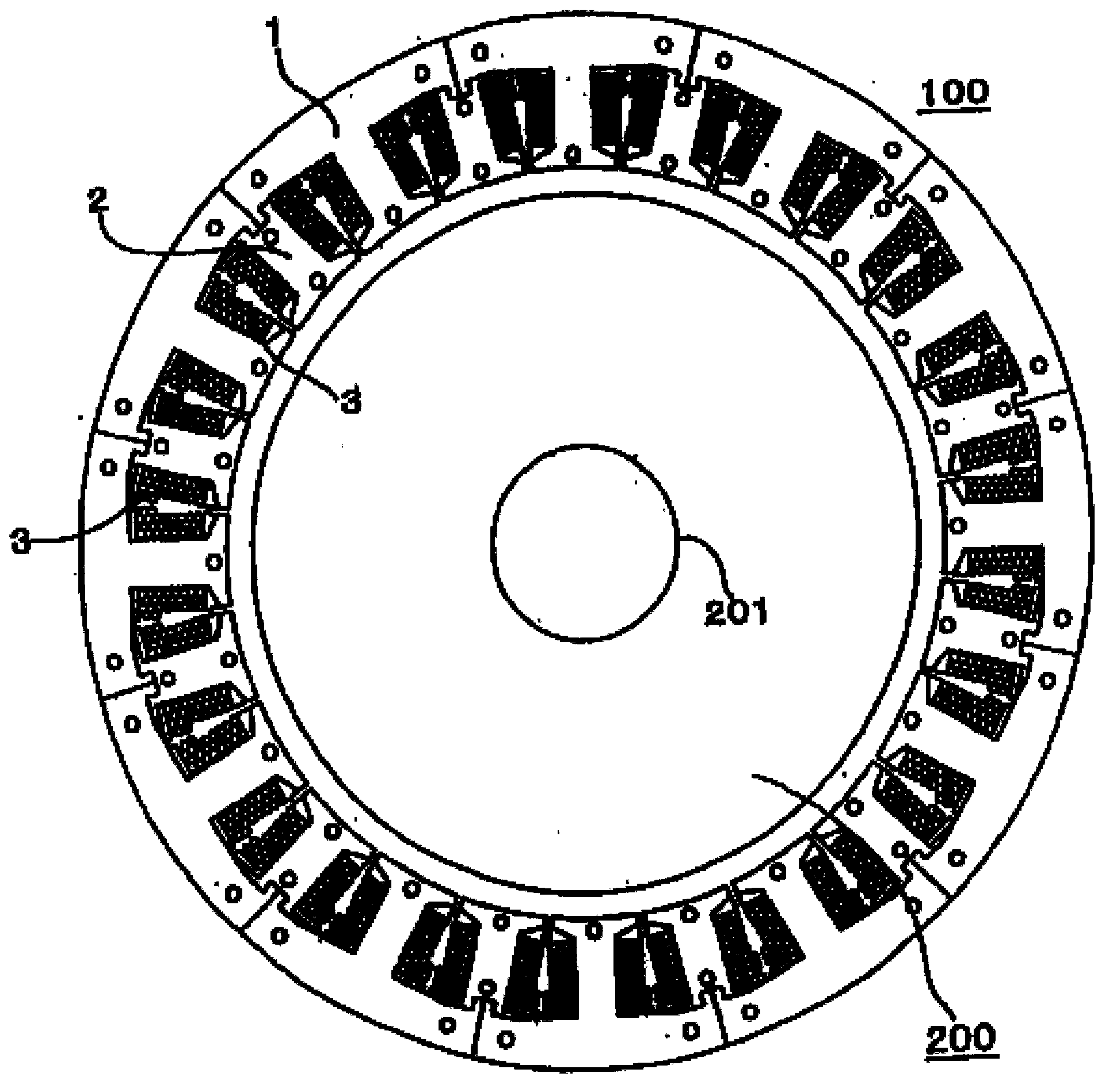
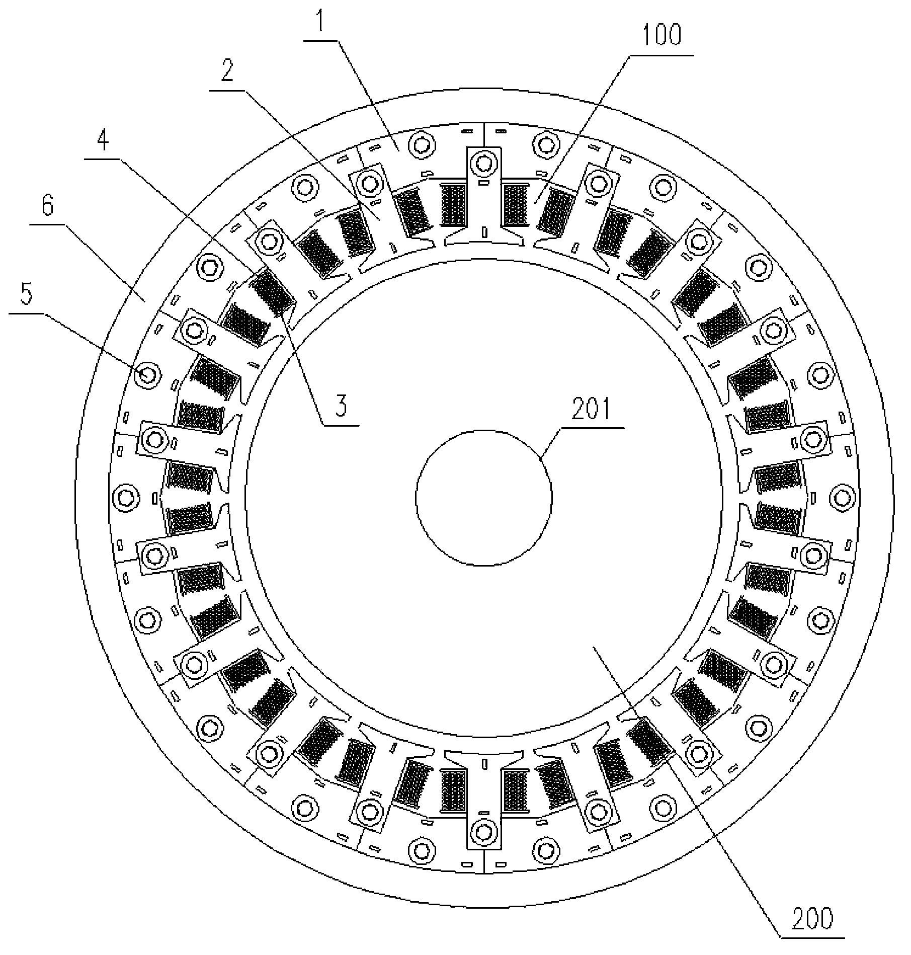
[0046] Such as image 3 Shown is the first embodiment of the stator of the rotating electrical machine of the present invention, the rotating electrical machine includes a stator 100, a rotor 200 mounted on a rotating shaft 201, the stator 100 and the rotor 200 are arranged opposite to each other through a prescribed gap.

[0047] Such as image 3 , Figure 4 As shown, the stator 100 of the rotating electrical machine includes a stator yoke 1, a stator tooth 2, a coil 3, an insulator 4, a mounting plate 6 and a plurality of fasteners 5, and in this embodiment, both the stator yoke 1 and the stator teeth 2 are 18 indivual.

[0048] The stator tooth 2 is formed by stacking steel plates of the shape shown in the figure according to the required number, and is integrally formed by punching and riveting interface 2b. The convex top 2c of the stator tooth has a mounting hole 2d along the axial direction, such as Figure 6 shown.

[0049] Same as the stator teeth 2, the stator y...


PUM


Abstract

The invention discloses a stator of a rotary motor, which comprises stator yokes, stator teeth, coils and insulators, wherein the stator teeth are provided with raised parts, and the stator yokes are provided with groove parts; the stator teeth and the groove parts of the stator yokes are arranged in the circumferential direction of the rotary motor in sequence through the raised parts; the raised parts of the stator teeth are positioned in the groove parts of the stator yokes; the coils twine on the stator teeth through the insulators. According to the stator structure, the stator teeth and the stator yokes are not easy to generate stress deformation due to the connection of the stator teeth and the stator yokes; the control of dimensional accuracy and positional accuracy is facilitated, so adverse influence cannot be generated on the performance of the rotary motor; in addition, the material utilization rate is high, the manufacture is easy, the production efficiency is high, and the manufacture of the stator of the rotary motor of a traction machine for an elevator is particularly facilitated.

Description

technical field [0001] The invention relates to a stator of a rotating electrical machine, in particular to a stator of a rotating electrical machine in an elevator traction machine. Background technique [0002] The currently commonly used traction machine for elevators generally provides driving force through a rotating motor. The rotating electrical machine is composed of a stator and a rotor, and the stator includes a stator core, a coil, and the like. The stator core usually adopts a whole core structure, including the stator yoke and stator teeth, and the stator yoke and stator teeth are integrated. The usual production method is: punching a single layer of silicon steel sheet through a punching machine into a single stator core punching sheet, A plurality of identical stator core punches are stacked to form a stator core. The monolithic iron core structure and manufacturing method have low utilization rate of silicon steel sheets, serious waste of materials, complex...

Claims


Application Information

Patent Timeline
Patent Type & Authority Applications(China)
IPC IPC(8): H02K1/14H02K1/18H02K3/46
CPCH02K15/022H02K1/148H02K1/185
Inventor 李伟李磊顾伟光李洁
Owner SHANGHAI MITSUBISHI ELEVATOR CO LTD
Learn More