
Controlling device and charging device of power factor correction circuit

A power factor improvement and control device technology, which can be applied to output power conversion devices, circuit devices, battery circuit devices, etc., and can solve problems such as hindering miniaturization/cost reduction.

Inactive Publication Date: 2014-03-26
OMRON AUTOMOTIVE ELECTRONICS CO LTD
View PDF12 Cites 4 Cited by
  • Summary
  • Abstract
  • Description
  • Claims
  • Application Information

AI Technical Summary

Problems solved by technology

Therefore, components such as an isolation amplifier are required, and further, an insulation distance needs to be ensured, which hinders miniaturization and cost reduction

Method used


Image

  • Controlling device and charging device of power factor correction circuit
  • Controlling device and charging device of power factor correction circuit
  • Controlling device and charging device of power factor correction circuit

Examples


Embodiment Construction

[0037] Hereinafter, embodiments of the present invention will be described with reference to the drawings. In the respective drawings, the same symbols are attached to the same parts or corresponding parts.

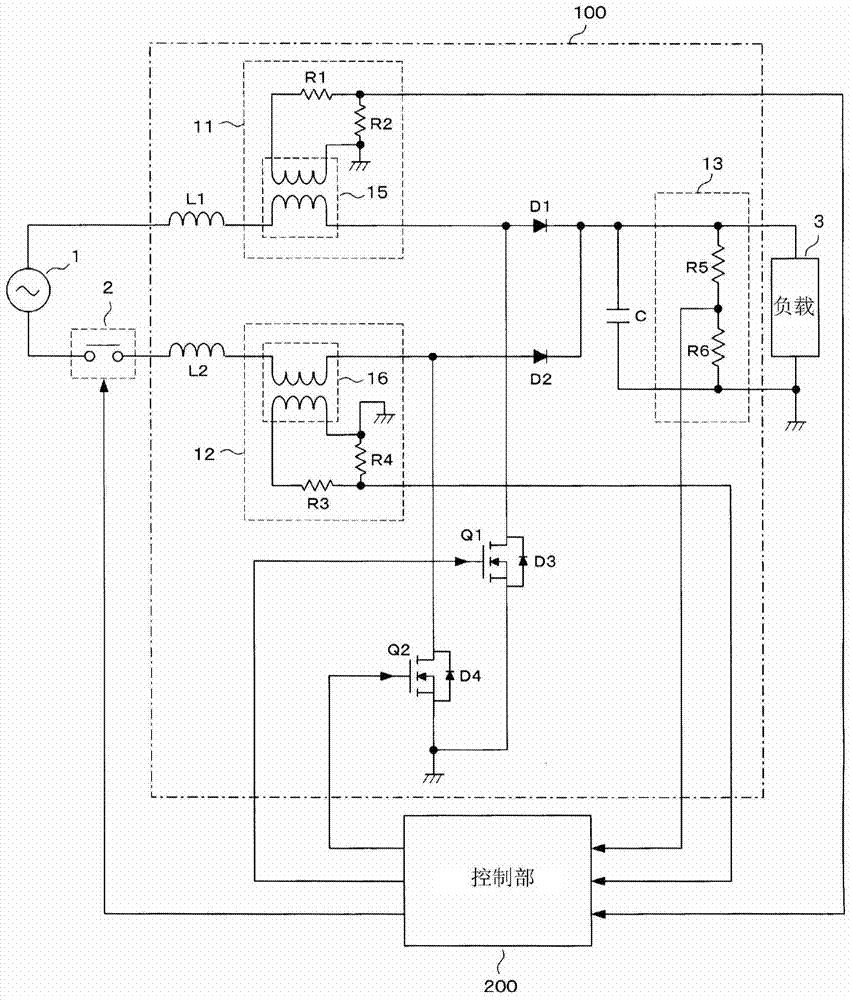
[0038] First, refer to figure 1 , to describe the structure of the embodiment. exist figure 1 Among them, a PFC (power factor improvement) circuit 100 is provided between an external AC power source 1 and a load 3 , and its operation is controlled by a control unit 200 . The AC power supply 1 is, for example, a commercial power supply of AC100V. Between the AC power supply 1 and the PFC circuit 100, a relay 2 for preventing inrush current is connected. Switching of the relay 2 is controlled by the control unit 200 . The control unit 200 is constituted by a microcomputer. The output terminal of the PFC circuit 100 is connected to the load 3 .

[0039] PFC circuit 100 has inductors L1 , L2 , diodes D1 , D2 , capacitor C, switching elements Q1 , Q2 , current detecti...


PUM


Abstract

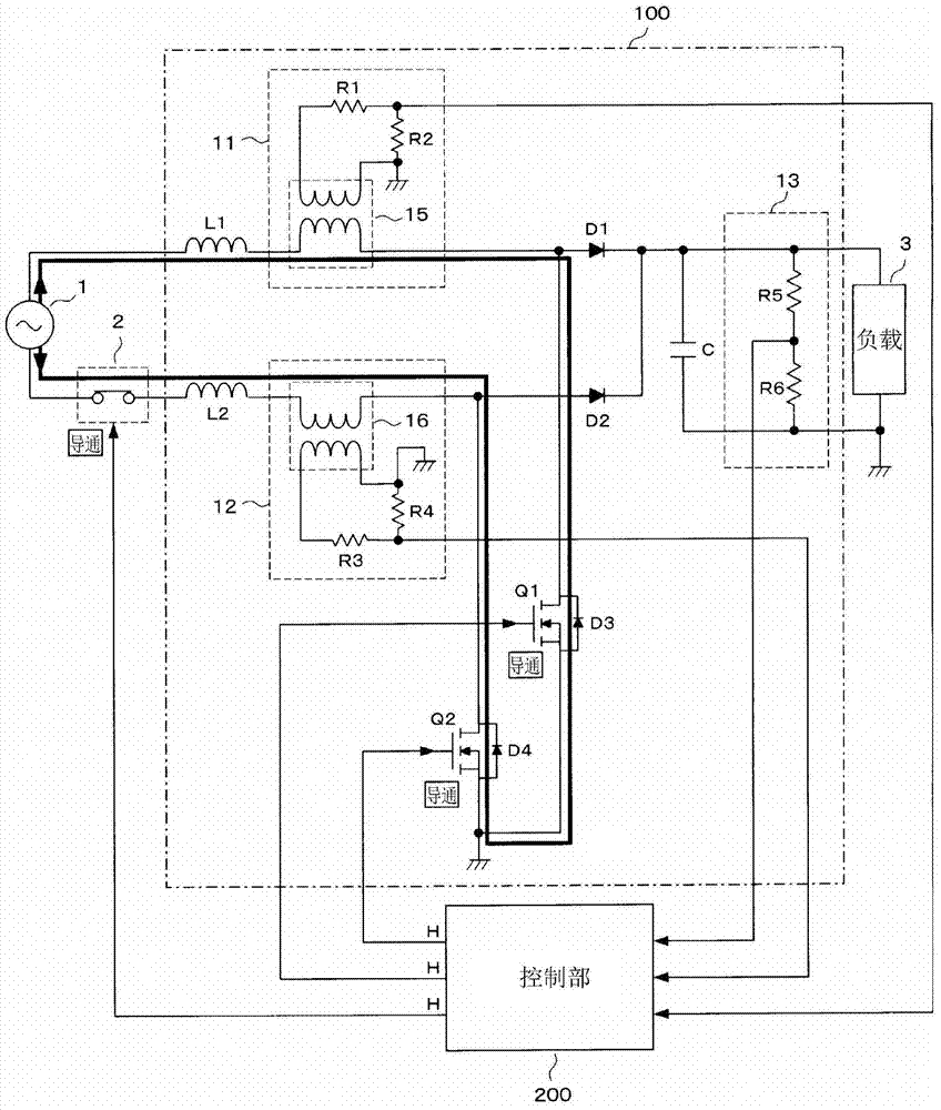
The present invention provides a controlling device and a charging device of a power factor correction circuit. Even a voltage detection circuit for detecting an input voltage is not arranged, desired actions also can be carried out. The controlling device of the PFC circuit comprises the PFC circuit (100) possessing the current detection circuits (11, 12) for detecting an input current and the voltage detection circuit (13) for detecting an output voltage, and a control part (200) for controlling the on-off actions of the switch elements (Q1, Q2) of the PFC circuit (100). The control part (200) enables the switch elements (Q1, Q2) to be fixed in the conduction state when the PFC circuit (100) is started, analyzes the waveform of the input current flowing the switch elements (Q1, Q2) from an AC power supply (1) according to the output of the current detection circuits (11, 12), and carries out the initialization processing to determine the input voltage of the PFC circuit (100) according to the analysis result.

Description

technical field [0001] The present invention relates to a control technology of a power factor improving circuit which makes the waveform of the input current close to the waveform of the input voltage to improve the power factor. Background technique [0002] In an electric vehicle or a hybrid vehicle, a high-voltage battery is mounted as a drive source of a running motor, and a charging device for charging the battery is provided (for example, refer to Patent Documents 1 and 2). Such a charging device generally includes a power factor improvement circuit (hereinafter, referred to as a PFC (Power Factor Correction) circuit). [0003] Figure 18 An example of a PFC circuit is shown. The PFC circuit 60 is a known circuit composed of an inductor L3, a diode D5, a capacitor C1, and a switching element Q3. The switching element Q3 is constituted by, for example, a MOS-FET, and performs a switching operation by being turned on / off according to a pulse signal from the control un...

Claims


Application Information

Patent Timeline
Patent Type & Authority Applications(China)
IPC IPC(8): H02M1/42H02J7/02H02M3/28H02M7/12
CPCH02M1/36H02J7/022H02M2001/0009H02J7/007H02M7/217H02M1/4225Y02B70/126H02J7/02H02J2207/20Y02B40/00Y02B70/10H02M1/0009H02M1/0085
Inventor 大元靖理几岛好广井户勇作
Owner OMRON AUTOMOTIVE ELECTRONICS CO LTD
Learn More