Fan heat dissipation device and method

A technology of heat dissipation device and heat dissipation method, which is applied in cooling/ventilation/heating transformation, pump control, non-variable-capacity pump, etc., can solve the problems of no alarm function, inability to adjust the fan speed, labor cost, etc., and achieve savings The effect of labor cost, simple structure and flexible design

Inactive Publication Date: 2014-03-26
PHICOMM (SHANGHAI) CO LTD
View PDF4 Cites 7 Cited by
  • Summary
  • Abstract
  • Description
  • Claims
  • Application Information

AI Technical Summary

Problems solved by technology

[0004] The technical problem to be solved by the present invention is to overcome the labor cost of using the ASIC chip to realize the heat dissipation of the equipment in the prior art, the inability to automatically adjust the fan speed according to the temperature of the equipment in a timely and accurate manner, and the lack of alarm Functional defects, provide a fan cooling device that uses the function of logic devices to automatically adjust the fan speed and alarm function according to the temperature of the device, and a fan cooling method that uses the fan cooling device to achieve

Method used


Image

  • Fan heat dissipation device and method
  • Fan heat dissipation device and method
  • Fan heat dissipation device and method

Examples


Embodiment 1

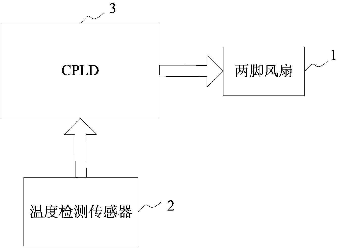
[0028] refer to figure 1 As shown, a fan cooling device includes a two-legged fan 1, a temperature detection sensor 2 and a CPLD3, the two-legged fan 1 is used to dissipate heat from a device (not shown in the figure), and the CPLD3 stores One-to-one correspondence of ten temperature ranges and ten rotational speeds;

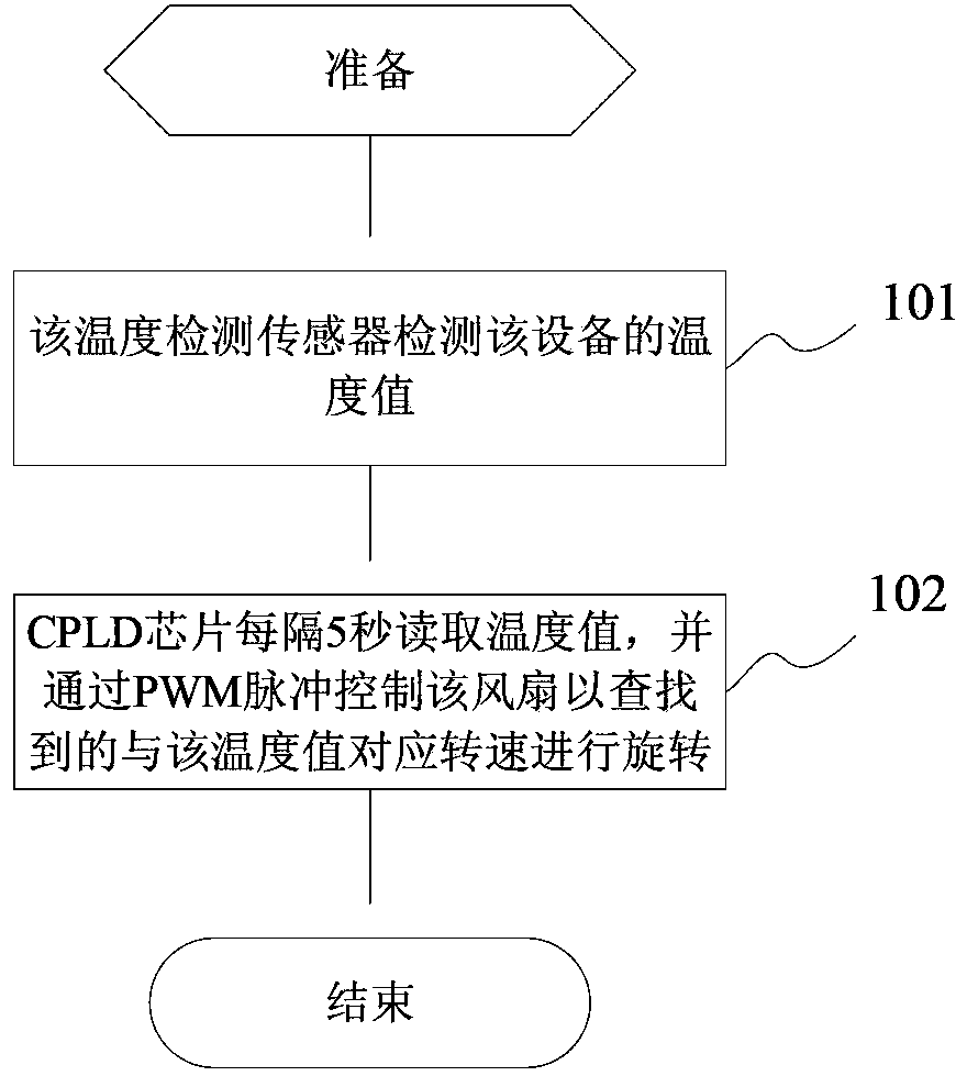
[0029] The temperature detection sensor 2 is used to detect the temperature value of the device;

[0030] The CPLD3 is used to read the temperature value at intervals (such as 5 seconds), and find the speed corresponding to the temperature range that includes the temperature value in the ten temperature ranges, and control the two pins through PWM pulses Fan 1 rotates at the found rotation speed. Of course, the time period can also be set to other values.

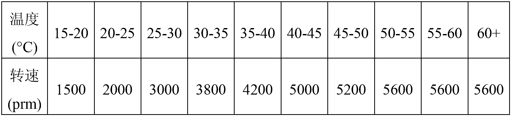
[0031] Among them, the corresponding relationship between the ten temperature ranges and ten rotational speeds stored in the CPLD3 is shown in the following table:

[0032]

[0033] figure 2 Shown is...

Embodiment 2

[0039] This embodiment differs from Embodiment 1 in that: the two-pin fan in the fan cooling device is replaced by a three-pin fan, the CPLD is replaced by an FPGA, and one of the three pins of the three-pin fan is an alarm pin, so in the device When the temperature is too high, the FPGA can realize the alarm function.

[0040] E.g:

[0041] When the temperature value of the device detected by the temperature detection sensor 2 is 75°C, after the FPGA reads the temperature value of 75°C, it finds the temperature interval including the temperature value of 75°C among the ten temperature intervals (60+)℃ corresponds to a speed of 5600 (prm), and the three-legged fan is controlled to rotate at the found speed of 5600 (prm) through PWM pulses. At the same time, the alarm pin included in the three-legged fan is passed through the I / O pin The high-level signal is transmitted to the FPGA, and the FPGA sends out an alarm reminder.

[0042] Other parts of this embodiment are identica...


PUM


Abstract

The invention discloses a fan heat dissipation device and method. The fan heat dissipation device comprises a fan, wherein the fan is used for performing heat dissipation to equipment; the fan heat dissipation device also comprises a temperature detection sensor and a logic device, wherein a plurality of temperature intervals and rotating speeds which are in one-to-one correspondence relation are stored in the logic device; the temperature detection sensor is used for detecting the temperature value of the equipment; and the logic device is used for reading the temperature value, searching rotating speeds corresponding to temperature intervals containing the temperature value, and controlling a fan to rotate at the researched rotating speeds. The device is flexible in design, has a simple structure, saves labor cost, can timely, accurately and automatically adjust the rotating speed of the fan according to the temperature of the equipment, and can realize an alarm function when the temperature of the equipment is too high.

Description

technical field [0001] The present invention relates to a heat dissipation device and method, in particular to a fan heat dissipation device and method. Background technique [0002] In the equipment standard provided by China Telecom, there are clear requirements for the operating environment of the equipment. During the operation of the equipment, excessive temperature of the equipment will significantly affect the normal operation of the equipment. Therefore, the heat dissipation problem of the equipment has become a very important factor affecting the normal operation of the equipment. [0003] At present, a fan is installed on the device to dissipate heat from the device. Generally, an ASIC (Application Specific Integrated Circuit) chip is used to realize this function. However, when the temperature of the device is too high, the fan speed needs to be manually adjusted. The method consumes labor costs, cannot automatically adjust the speed of the fan according to the t...

Claims


Application Information

Patent Timeline
Patent Type & Authority Applications(China)
IPC IPC(8): H05K7/20F04D27/00
Inventor 李军
Owner PHICOMM (SHANGHAI) CO LTD
Why Eureka
Try Eureka