Lithium energy storage device
An energy storage device, lithium titanium oxide technology, applied in circuit devices, battery circuit devices, lithium batteries, etc., can solve problems such as low conductivity, low mobility, and limitations
- Summary
- Abstract
- Description
- Claims
- Application Information
AI Technical Summary
Problems solved by technology
Method used
Image

Examples
Embodiment 1
[0241] Embodiment 1: preparation and test lithium salt
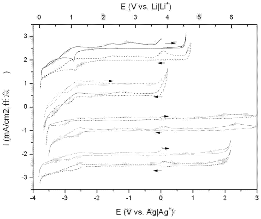
[0242] Preliminary experiments were performed to determine the electrochemical windows of the cyano-based anions described herein. figure 2 The electrochemical window is shown for a salt-free ionic liquid with the same cation, ie, N-butyl-N-methyl-pyrrolidinium. It can be found that the electrochemical window of ionic liquids containing cyano moieties is inferior compared to N,N-pyrrolidinium bis(trifluoromethanesulfonyl)imide ionic liquids. Of all the cyano-based ionic liquids that have been scanned, one particularly advantageous system is pyrrolidinium dicyanamide.
[0243] Experiments were conducted to find out whether any lithium salts (i.e., dopants) that were dissolved in ionic liquid electrolytes to provide a source of migratory lithium ions could be effectively used with the above-mentioned electrolytes containing dicyanamide anions.
[0244] At room temperature, lithium salts LiDCA, LiBF 4 , LiBOB, LiTFSI, a...
Embodiment 2
[0248] Embodiment 2: Test C 4 C 1 pyr DCA0.5mol / kg LiDCA132ppm H 2 Electrolyte composed of O
[0249] Lithium cycling within the electrolyte was tested using cyclic voltammetry. The working electrode was a platinum disc electrode with a diameter of 500 μm, which was first polished with 0.05 μm alumina and dried before use. The counter electrode is a platinum wire with a surface area many times higher than that of the working electrode. The reference electrode consisted of a silver wire immersed in a 10 mM solution of silver trifluoromethanesulfonate in N-butyl-N-methylpyrrolidinium bis(trifluoromethanesulfonyl)imide, and Isolated from the main solution by a glass frit.
[0250] For each scan, the working electrode was cycled from potential 0V (relative to reference) to -4.3V (relative to reference) and back to 0V (relative to reference). The scan rate was 50 mV / s, and the experiments were performed at room temperature (~23 °C) in a glove box filled with high-purity argon...
Embodiment 3
[0252] Example 3: Test by C 4 C 1 pyr DCA0.5mol / kg LiDCA285ppm H 2 Electrolyte composed of O
[0253] Under the conditions of Example 2 above, lithium cycling in the electrolyte was tested using cyclic voltammetry, but the electrolyte contained 285 ppm H 2 O.
[0254] Figure 5 It was shown that reversible lithium deposition also occurs in this electrolyte with a slightly higher water content (285 ppm) compared to the previous example (132 ppm). Figure 4 The peak current is lower, suggesting stronger passivation. Although the peak height is lower, this electrolyte is somewhat more stable from cycle to cycle compared to the drier example.
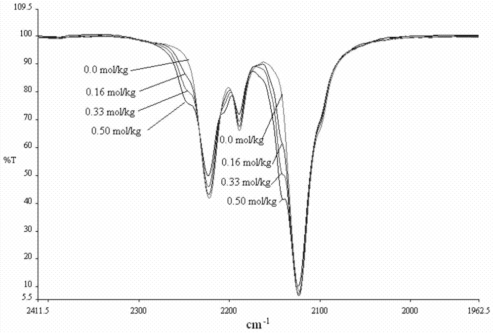
[0255] The peak currents for electroplated Li (Li++e-◇Li) and reduced Li (Li◇Li++e-) have been plotted as a function of water content in the solution. Moisture content was determined by using Karl-Fischer. It was found that, if Figure 6 As shown, in order to maximize the plating and deplating of Li in solution, a critical amount n...
PUM
 Abstract
Description
Claims
Application Information
 - R&D Engineer
- R&D Manager
- IP Professional
- Industry Leading Data Capabilities
- Powerful AI technology
- Patent DNA Extraction
Browse by: Latest US Patents, China's latest patents, Technical Efficacy Thesaurus, Application Domain, Technology Topic.
© 2024 PatSnap. All rights reserved.Legal|Privacy policy|Modern Slavery Act Transparency Statement|Sitemap