Rotary distributing mechanism

A material distribution mechanism and material distribution shaft technology, applied in metal processing, metal processing equipment, manufacturing tools, etc., can solve the problems of low work efficiency, time-consuming and labor-intensive assembly, and high labor intensity, and achieve the effect of high work efficiency.

Active Publication Date: 2014-04-02
BOZHON PRECISION IND TECH CO LTD
View PDF6 Cites 6 Cited by
  • Summary
  • Abstract
  • Description
  • Claims
  • Application Information

AI Technical Summary

Problems solved by technology

However, the assembly of screws and nuts is generally done manually. Due to the large number of screws and nuts of different specifications, the assembly is time-consuming, labor-intensive, and low-efficiency.

Method used


Image

  • Rotary distributing mechanism
  • Rotary distributing mechanism
  • Rotary distributing mechanism

Examples


Embodiment Construction

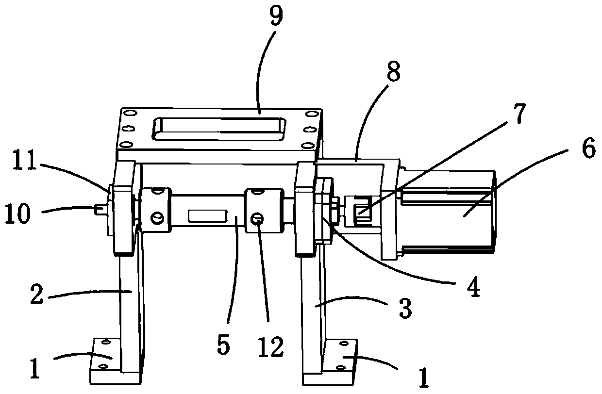
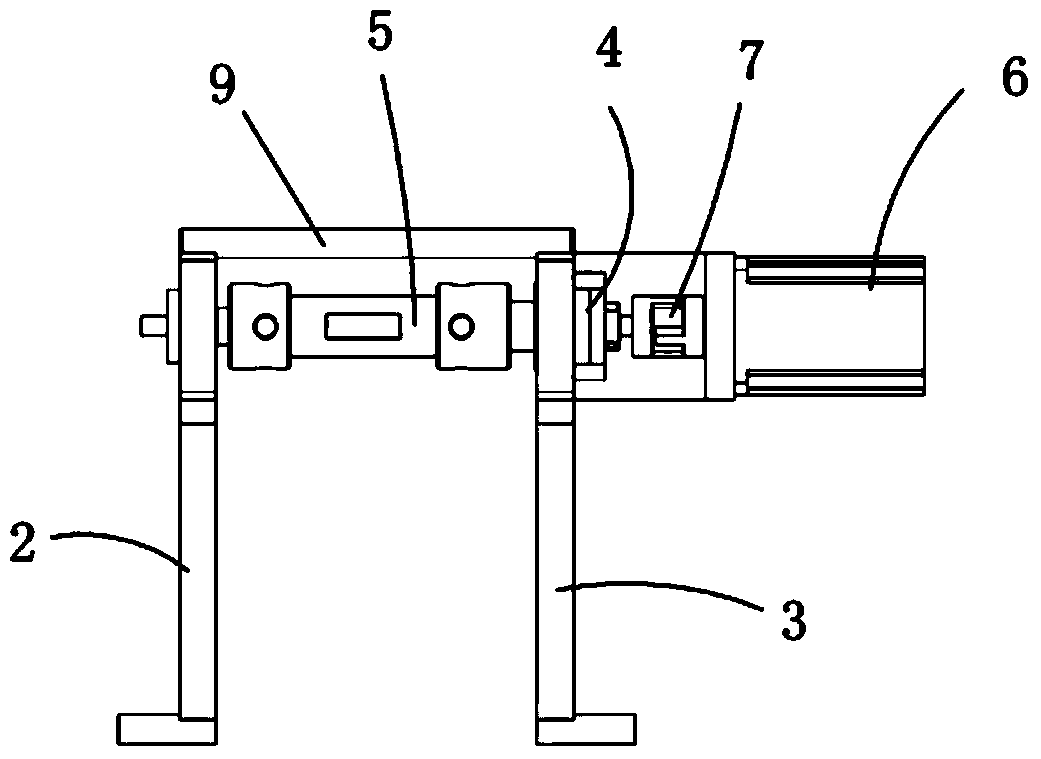
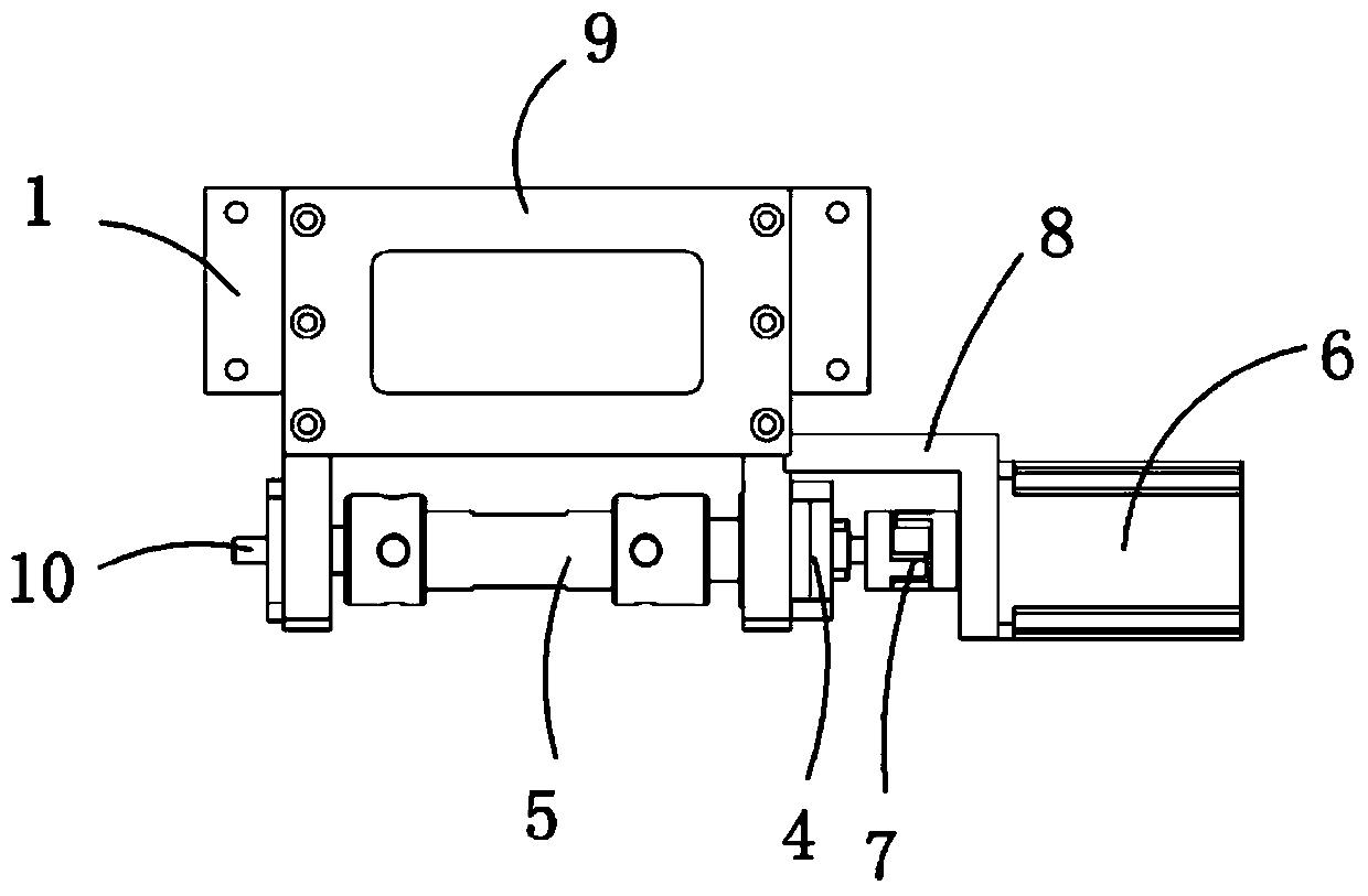
[0017] Examples, see attached Figure 1~3 , a rotary material distribution mechanism, which includes an installation bottom block 1, a left bearing support block 2, a right bearing support block 3, a material distribution shaft bearing seat 4, a material distribution shaft 5, a stepping motor 6, a coupling 7, a distribution shaft Material shaft motor mounting plate 8, connecting fixed plate 9, mandrel 10 and mandrel shaft seat 11, the described installation bottom block has two, is respectively left installation bottom block and right installation bottom block, and described left bearing support block is installed On the left installation bottom block, the right bearing support block is installed on the right installation bottom block; a mandrel shaft seat is installed on the left bearing support block, and a mandrel shaft is installed on the mandrel shaft seat; the right bearing supports The material distribution shaft bearing seat is installed on the block, the material dist...


PUM


Abstract

The invention relates to a rotary distributing mechanism. A left bearing supporting block and a right bearing supporting block are respectively arranged on a left mounting bottom block and a right mounting bottom block; a mandrel seat is arranged on the left bearing supporting block; a mandrel is arranged on the mandrel seat; a distributing shaft bearing block is arranged on the right bearing supporting block; a distributing shaft motor mounting plate is arranged on the right side of the right bearing supporting block; a stepping motor is arranged on the distributing shaft motor mounting plate; the front end of the stepping motor is connected with a distributing shaft through a coupler; the distributing is supported by the distributing shaft bearing block; the mandrel is sleeved in the distributing shaft; four distributing holes are formed in the distributing shaft and comprise two perpendicular distributing holes and two horizontal distributing holes; a screw can be arranged in one of the horizontal distributing holes; a through hole which is perpendicular to the mandrel is formed in the mandrel and is vertical; the stepping motor drives the distributing shaft to rotate at an angle of 90 degrees anticlockwise; and the two horizontal distributing holes in the distributing shaft are perpendicular to each other, and are concentric with the through hole in the mandrel, so that the screw is guided to the through hole.

Description

Technical field: [0001] The invention relates to the field of equipment of a rotary material distribution mechanism, in particular to a rotary material distribution mechanism for screw material distribution. Background technique: [0002] When the screws and nuts are used together, it is necessary to assemble the screws and the nuts together, and transport the matched screws and nuts to the desired position for use, which is convenient for use. The assembly of screws and nuts is generally done manually. Since there are so many screws and nuts of different specifications, the assembly is time-consuming, labor-intensive, and inefficient. Invention content: [0003] The object of the present invention is to provide a rotary feeding mechanism for the deficiencies of the prior art, which can rotate the screw and deliver it to the standard working position, so as to prepare for the next step of assembling with the nut. [0004] Technical solutions of the present invention are a...

Claims


Application Information

Patent Timeline
Patent Type & Authority Applications(China)
IPC IPC(8): B23P19/00
CPCB23P19/007
Inventor 吕绍林杨愉强吴小平邓瑞林王票
Owner BOZHON PRECISION IND TECH CO LTD
Why Eureka
Try Eureka