Eureka AIR delivers breakthrough ideas for toughest innovation challenges, trusted by R&D personnel around the world.

High-rise ceramic tile transportation system

A transportation system and ceramic tile technology, which is applied in the mechanical field, can solve the problems of dust and sand on the stairs and other household doors, increase the labor intensity of decoration workers, and large tile size.

Inactive Publication Date: 2014-04-02
JIAXING KAILY METALS & PLASTICS
View PDF4 Cites 13 Cited by
  • Summary
  • Abstract
  • Description
  • Claims
  • Application Information

AI Technical Summary

Problems solved by technology

[0003] This kind of residence will encounter many problems when decorating. Residents on the 3rd to 6th floors must manually carry construction tools such as cement, bricks and tiles upstairs. , and the cost of cement and bricks is low and not easy to be broken, they can still be transported manually. For ceramic tiles, which are fragile and costly decoration products, due to the large size of the tiles, it is inconvenient to hold them manually, which further improves its performance. Labor intensity, and care must be taken to avoid damaging the tiles while moving, which further reduces the efficiency of tile handling
Moreover, since it will definitely pass through the doors of other residents during transportation, the dust on the tiles and their packaging will make the stairs and other doorways of other residents covered with dust and sand.
[0004] The above factors have seriously restricted the development of the decoration industry, increased the labor intensity of the decoration workers, and greatly reduced the work efficiency of the decoration workers.

Method used

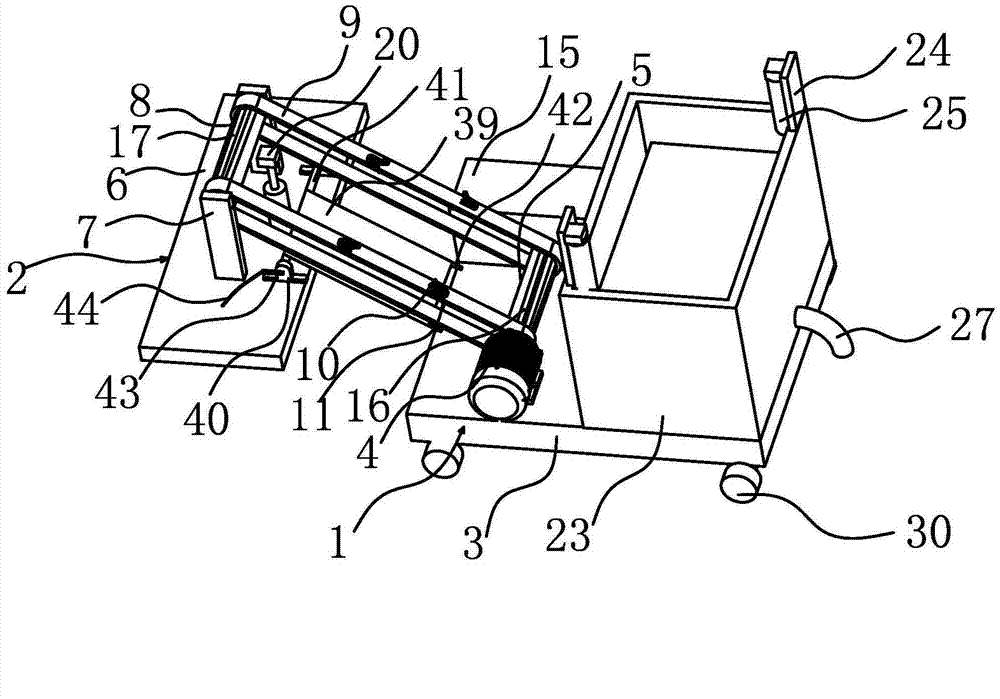
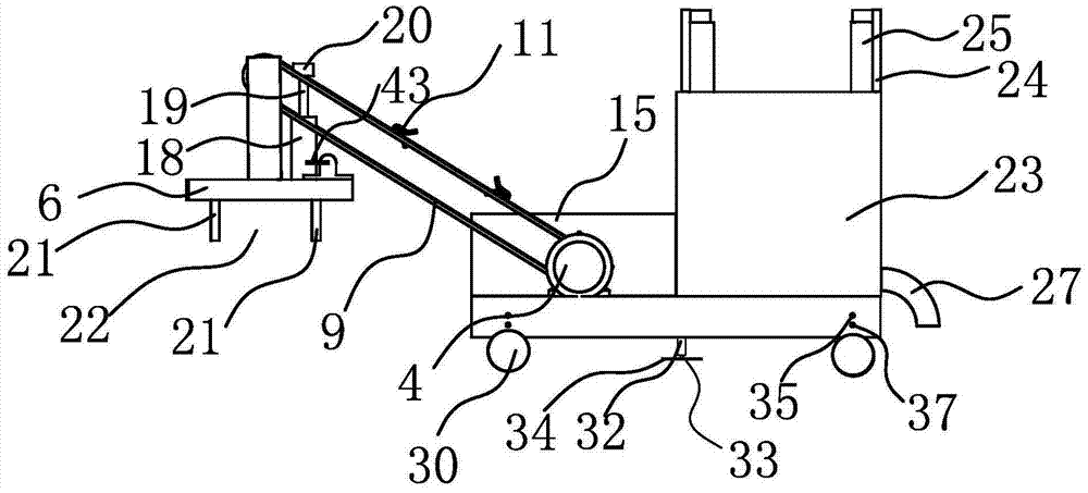
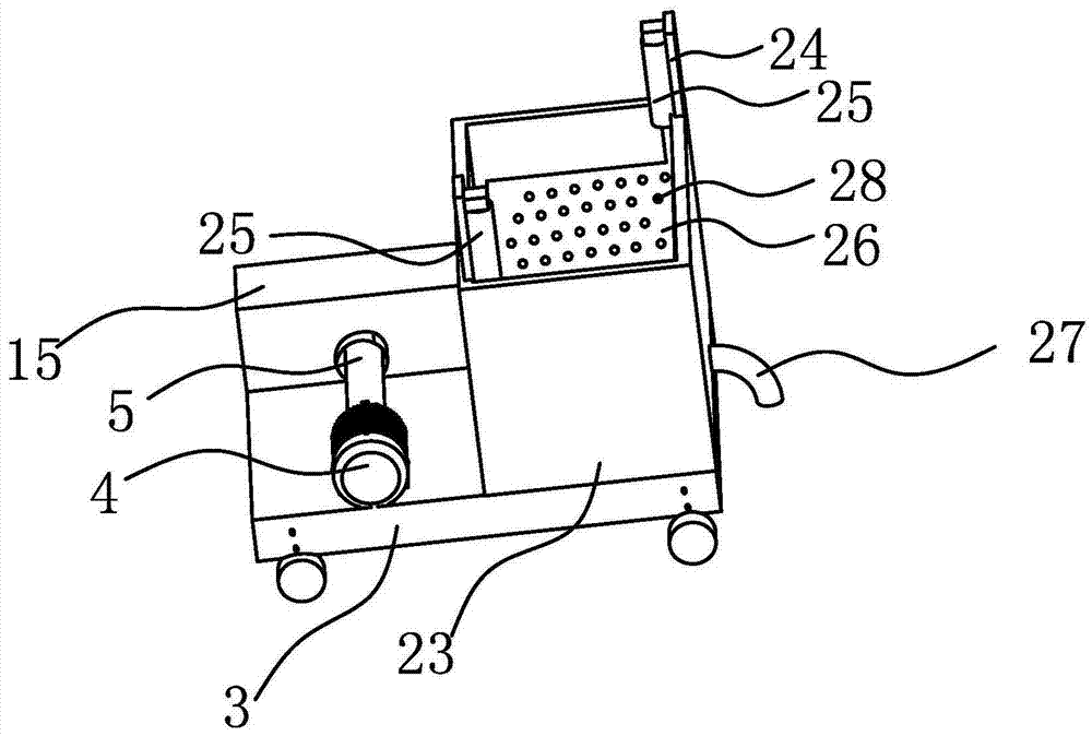

Image

  • High-rise ceramic tile transportation system
  • High-rise ceramic tile transportation system
  • High-rise ceramic tile transportation system

Examples


Embodiment Construction

[0054] The following are specific embodiments of the present invention and in conjunction with the accompanying drawings, the technical solutions of the present invention are further described, but the present invention is not limited to these embodiments.

[0055] like figure 1 As shown, the transportation system includes a feeding device 1 and a feeding device 2; the feeding device 1 includes a first base plate 3 arranged on the outdoor ground, and a motor 4 is fixed on the first base plate 3, and the output end of the motor 4 A driving shaft 5 is fixedly connected; the unloading device 2 includes a second bottom plate 6 arranged at the window of the household, and two support columns 7 are vertically fixed on the upper surface of the second bottom plate 6, and the unloading device 2 also includes a The driven shaft 8 parallel to the driving shaft 5, the two ends of the driven shaft 8 are respectively rotated on the two support columns 7; the transportation system also inclu...


PUM


Abstract

The invention provides a high-rise ceramic tile transportation system, and belongs to the technical field of machinery. The high-rise ceramic tile transportation system solves the technical problems of low transportation efficiency of ceramic tiles in high-rise decoration and the like in the prior art. The transportation system comprises a feeding device, a discharging device and at least two conveying belts, the feeding device comprises a first bottom plate arranged on the outdoor ground, a motor is fixedly arranged on the first bottom plate, an output end of the motor is fixedly connected with a driving shaft, the discharging device comprises a second bottom plate and a driven shaft, the second bottom plate is arranged at a resident window, two support columns are vertically and fixedly arranged on the upper surface of the second bottom plate, the driven shaft is parallel to the driving shaft, two ends of the driven shaft are rotatably arranged on the two support columns respectively, two ends of each conveying belt are sleeved on the driving shaft and the driven shaft respectively, the conveying belts, the driving shaft and the driven shaft can synchronously rotate, and a clamping mechanism capable of clamping the ceramic tiles is further arranged on each conveying belt. The high-rise ceramic tile transportation system has the advantages of high transportation efficiency and the like.

Description

technical field [0001] The invention belongs to the technical field of machinery and relates to a high-rise transportation system for ceramic tiles. Background technique [0002] With the increasing shortage of land resources, existing buildings tend to be more and more high-rise. However, in our country, it is stipulated that elevators must be installed in residential buildings with seven floors and above or residential entrance floors that are more than 16m above the outdoor design ground. Therefore, many residential buildings are designed as 6th floors in order to reduce the cost of installing elevators. [0003] This kind of residence will encounter many problems when decorating. Residents on the 3rd to 6th floors must manually carry construction tools such as cement, bricks and tiles upstairs. , and the cost of cement and bricks is low and not easy to be broken, they can still be transported manually. For ceramic tiles, which are fragile and costly decoration products,...

Claims


Application Information

Patent Timeline
IPC IPC(8): B65G17/14B65G17/30
Inventor 朱炳
Owner JIAXING KAILY METALS & PLASTICS
Why Eureka
Eureka Blog
Learn More