
A Circular Transmission Mechanism and Circular Transmission Method for Tunnel Furnace Tray

A technology of circular transmission and tunnel furnace, which is applied in the direction of conveyor, transportation and packaging, etc., and can solve the problems of failure to realize circulation and inconvenient automatic production of products, etc.

Active Publication Date: 2016-06-01
XIAMEN TOPTECH ELECTRONICS
View PDF7 Cites 0 Cited by
  • Summary
  • Abstract
  • Description
  • Claims
  • Application Information

AI Technical Summary

Problems solved by technology

In this kind of tunnel furnace, since the transfer of the tray is not realized, it is not convenient for the automatic production of the product.

Method used


Image

  • A Circular Transmission Mechanism and Circular Transmission Method for Tunnel Furnace Tray
  • A Circular Transmission Mechanism and Circular Transmission Method for Tunnel Furnace Tray
  • A Circular Transmission Mechanism and Circular Transmission Method for Tunnel Furnace Tray

Examples


Embodiment

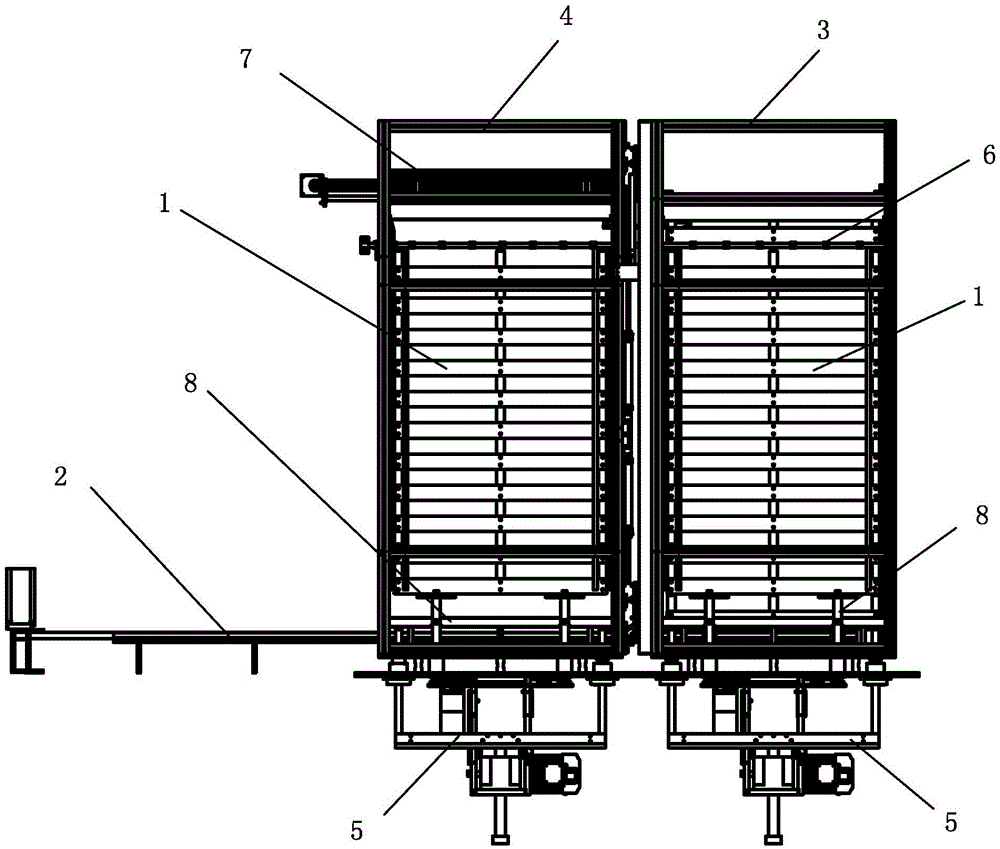
[0056] see Figure 1 to Figure 15 As shown, a kind of tunnel furnace tray circulating transmission mechanism of the present invention includes:

[0057] Carrier 1;

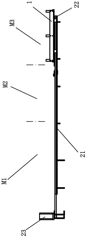
[0058] A horizontal reciprocating mechanism 2 has a horizontal track 21 and a carrier plate 22 capable of reciprocating movement on the horizontal track, and the horizontal track is sequentially provided with a first position M1, a second position M2 and a third position M3;

[0059] A drying box 3 is installed in a position suitable for the third position M3 of the horizontal track, the drying box 3 is provided with a drying chamber along the vertical, the third position M3 of the horizontal track extends into the bottom of the drying chamber;

[0060] A cooling box 4 is installed in a position suitable for the second position M2 of the horizontal track, the cooling box 4 is provided with a vertical cooling chamber, and the second position M2 of the horizontal track extends into the the bottom of the cooling c...


PUM


Abstract

The invention discloses a tunnel furnace pallet circulation transfer mechanism and a circulation transfer method thereof. The tunnel furnace pallet circulation transfer mechanism comprises a pallet, a horizontal reciprocating movement mechanism, a drying oven, a cooling tank, a lifting mechanism, a rotating moving track, a feeding and discharging mechanism and a synchronous rotation mechanism. The horizontal reciprocating movement mechanism, the drying oven, the cooling tank, the lifting mechanism, the rotating moving track, the feeding and discharging mechanism and the synchronous rotation mechanism are combined together ingeniously, thus the circulation transfer of the pallet can be realized during the processes of drying and cooling products when the pallet passes through a tunnel furnace, and the use of an automatic production line is facilitated.

Description

technical field [0001] The invention relates to a transmission mechanism of a tunnel furnace tray, in particular to a tunnel furnace tray circulation transmission mechanism and a circulation transmission method thereof. Background technique [0002] A tunnel furnace in the prior art refers to a device for drying and cooling products, and such a tunnel furnace usually includes a drying device and a cooling device. The drying device and cooling device of this tunnel furnace are all designed to be strip-shaped, that is, the drying and cooling of the product can be realized during the conveying process of the product along a straight line. The drying device and cooling device of this tunnel furnace The cooling device is usually installed on the conveying track, and the product is moved on the conveying track, so as to realize the drying and cooling of the product. In the process of drying and cooling the product, usually the product to be dried and cooled is placed on the carri...

Claims


Application Information

Patent Timeline
Patent Type & Authority Patents(China)
IPC IPC(8): B65G25/02
Inventor 江元武郑锦义黄朝晖
Owner XIAMEN TOPTECH ELECTRONICS
Learn More