Battery arrangement structure and arrangement method

A battery and battery compartment technology, applied in the direction of structural parts, assembled battery machines, battery pack components, etc., can solve the problems of mutual influence of batteries, inability to store multiple batteries well, safety accidents, etc., and achieve unsafe and Compact and reliable storage, improving space utilization, ensuring stability and safety

Pending Publication Date: 2021-07-23
DONGGUAN YANGTIAN ELECTRONICS TECH +1
View PDF0 Cites 0 Cited by
  • Summary
  • Abstract
  • Description
  • Claims
  • Application Information

AI Technical Summary

Problems solved by technology

[0002] With the popularization of electric bicycles and electric vehicles, batteries have increasingly become an indispensable energy tool in life, and batteries often need to be charged and stored properly. During the charging and storage of batteries, if multiple batteries There are defects in placement, which will not only cause mutual influence between multiple batteries, but may also cause safety accidents
[0003] The inventors have discovered that multiple batteries cannot be stored well in the prior art, and how to connect multiple batteries to an external power supply stably and efficiently, and how to ensure that the overall structure of multiple batteries is compact and reliable when they are safely stored, How to improve the space utilization of multiple batteries and how to ensure the efficient circulation of batteries in the power storage cabinet has become a difficult point in the charging and storage of multiple batteries.

Method used


Image

  • Battery arrangement structure and arrangement method
  • Battery arrangement structure and arrangement method
  • Battery arrangement structure and arrangement method

Examples


Embodiment 1

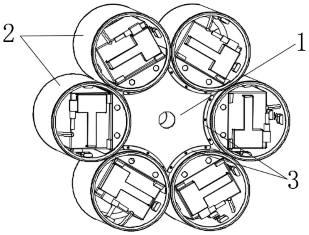
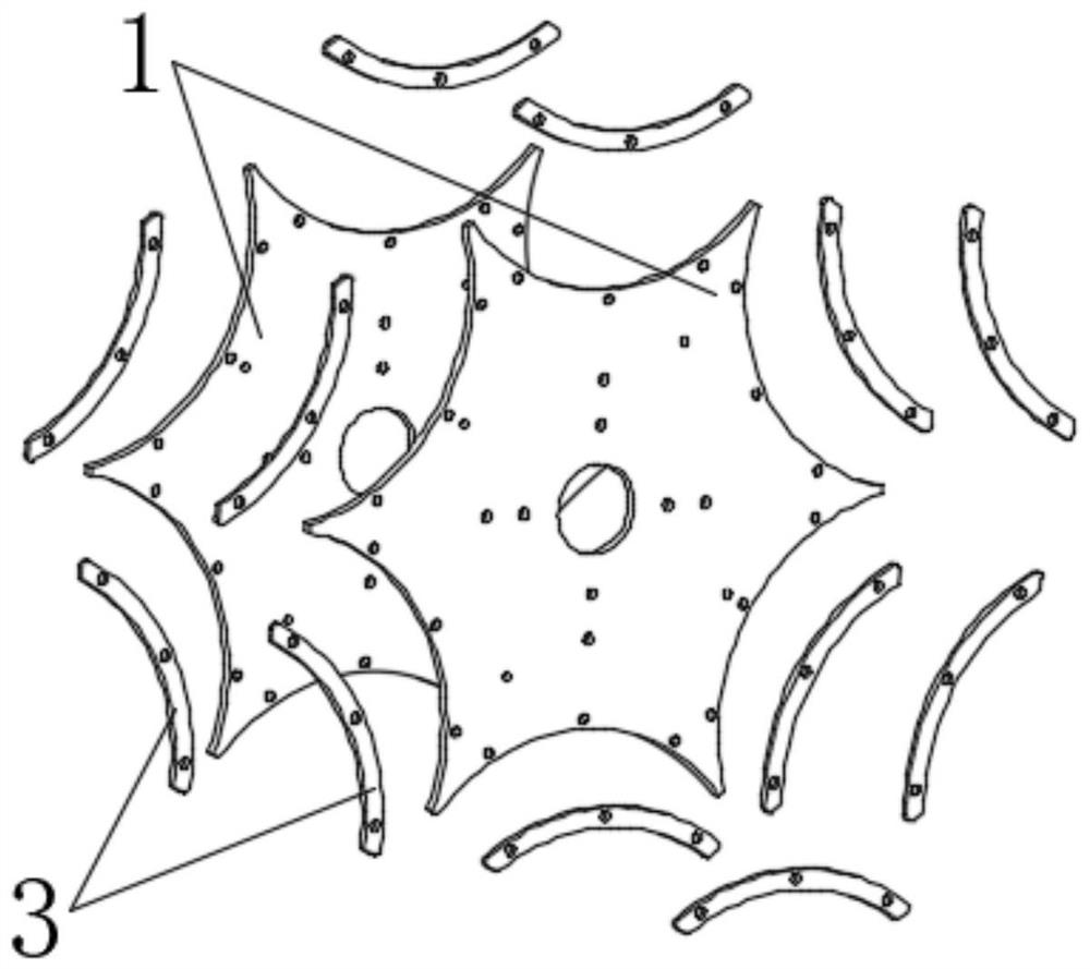
[0035] A battery arrangement structure, such as Figure 1~3 As shown, including the support plate 1 and the battery compartment 2, the side of the support plate 1 is evenly provided with a plurality of concave arcs, the support plate 1 is arranged as a rotationally symmetrical structure, and a plurality of battery compartments 2 are arranged around the side of the support plate 1, each The outer edge of each battery compartment 2 corresponds to each concave arc one by one.

[0036] Among them, the number of battery compartments 2 and concave arcs is 6, and the circle formed by the centers of 6 battery compartments 2 and the circles formed by the vertices of 6 concave arcs are concentric circles, so that the circumferential direction of each battery compartment 2 can be guaranteed. It is stable and safe during rotation, and the outer edge of the battery compartment 2 corresponds to each concave arc one by one, so that the arrangement structure is the densest overall structure, ...

Embodiment 2

[0049] A battery arrangement method such as Figure 6 shown, including the following steps:

[0050] Evenly set a plurality of concave arcs of equal size on the side of the support plate 1, so that each concave arc equally divides the side of the support plate 1;

[0051] A battery compartment 2 is installed on each concave arc, and the outer edge of each battery compartment 2 corresponds to each concave arc;

[0052] A plurality of battery compartments 2 containing batteries are lined up on the side of the support plate 1 , and the outer edges of the plurality of battery compartments 2 touch each other.

[0053] Preferably, each concave arc completely bisects the sides of the support plate 1, so that the structure of the support plate 1 is more uniform.

[0054] Preferably, there are 6 concave arcs and 6 battery compartments 2, and the height of each battery compartment 2 is equal.

[0055] Obviously, through the above-mentioned arrangement, the six battery compartments 2 ...

Embodiment 3

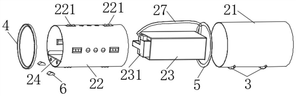
[0057] The difference between this embodiment and Embodiment 1 is that in order to improve the heat dissipation efficiency of the second cabin body 22, the top plate 242 is provided with air holes communicating with the first cavity 26 and the second cavity 27 at the same time, and a plurality of air holes are evenly distributed on the top plate 242, and the plurality of air holes correspond to the plurality of through holes provided on the upper side wall and the lower side wall of the second cabin body 22, wherein both the air holes and the through holes have good ventilation and heat dissipation performance, so that the battery module 23 can be effectively improved. The heat dissipation efficiency during charging inside the second compartment body 22 improves the service life of the battery compartment 2 .

[0058] Other structures of this embodiment are the same as those of Embodiment 1, and will not be repeated here.


PUM


Abstract

The invention belongs to the technical field of power supply modules and particularly relates to a battery arrangement structure. The structure comprises a supporting plate and a plurality of battery cabins, wherein a plurality of concave arcs are evenly arranged on the side portion of the supporting plate, the supporting plate is of a rotational symmetry structure, the battery cabins are arranged around the side portion of the supporting plate, and outer edges of the battery cabins correspond to the concave arcs in a one-to-one mode. According to the structure, a plurality of battery cabins can be tightly arranged, the space utilization rate of the whole structure is effectively improved, and each battery cabin can be uniformly stressed during circumferential rotation, so stability and safety of the whole structure are guaranteed. In addition, the invention also provides a battery arrangement method.

Description

technical field [0001] The invention belongs to the technical field of power supply modules, and in particular relates to a battery arrangement structure and arrangement method. Background technique [0002] With the popularity of electric bicycles and electric vehicles, batteries have increasingly become an indispensable energy tool in life, and batteries often need to be charged and stored properly. During the charging and storage of batteries, if multiple batteries There are defects in placement, which will not only cause mutual influence between multiple batteries, but may also cause safety accidents. [0003] The inventor has found that multiple batteries cannot be stored well in the prior art, and how to connect multiple batteries to an external power supply stably and efficiently, and how to ensure that the overall structure of multiple batteries is compact and reliable when they are safely stored, How to improve the space utilization of multiple batteries and how to...

Claims


Application Information

Patent Timeline
Patent Type & Authority Applications(China)
IPC IPC(8): H01M50/244H01M50/209H01M50/258H01M50/298H01M50/249H01M50/502H01M10/04
CPCH01M10/0404Y02P70/50
Inventor 赖逸新蒯敬瑨王军伟刘发厚
Owner DONGGUAN YANGTIAN ELECTRONICS TECH
Why Eureka
Try Eureka