
A solution sampling mixer

A stirrer and solution technology, applied in the field of solution sampling stirrers, can solve the problems of large storage equipment, uneven content in upper and lower parts, and easily scalded personnel, etc., achieving reliable sampling and analysis results, solving uneven solution, Simple and easy to operate effect

Active Publication Date: 2015-10-28
ANHUI WANBEI COAL REFCO GRP LTD HANSHAN HENGTAI NONMETALLIC MATERIALS BRANCH
View PDF5 Cites 0 Cited by
  • Summary
  • Abstract
  • Description
  • Claims
  • Application Information

AI Technical Summary

Problems solved by technology

In practice, due to the easy splashing of the solution, the storage equipment is a large tank. In addition, due to the high temperature and corrosion properties of some solutions, it is difficult to sample and analyze it.
For example, when sampling a tank car transporting hot concentrated ammonium nitrate solution, the operator must stand on the tank car, open the corresponding valve on the top of the tank car, put it in with a bucket, and manually pump out the solution and put it into the analytical instrument; but because the solution is a hot concentrated substance , easy to burn people
Another example is when sampling in the nitric acid tank area, the operator must stand on the storage tank and use a hanging bottle to take a deep sample from the manhole on the top of the tank. Since nitric acid is a highly toxic substance and has strong corrosion, it is unsafe and time-consuming.
[0003] In addition, since the sampling is basically taken from the upper part of the tank, some solutions have uneven content in the upper and lower parts of the tank due to specific gravity, precipitation, etc., which leads to inaccurate sampling
For example, hot concentrated ammonium nitrate solution and nitric acid solution are easy to separate layers, and the specific gravity of the bottom is often higher than that of the top, resulting in a large error between the sample analysis results and the actual

Method used


Image

  • A solution sampling mixer

Examples


Embodiment Construction

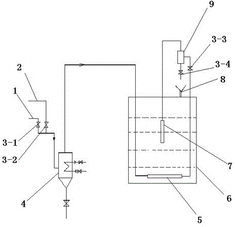
[0020] Such as figure 1 Shown, a kind of solution sampling stirrer comprises solution storage tank 6, and the bottom of described solution storage tank 6 is provided with first gas distributor 5 at 15-25cm from its bottom end face, and the input end of first gas distributor 5 is connected There is a cooler 4, and the input ends of the cooler 4 are respectively connected with the air pipe 1 and the nitrogen pipe 2; the output end of the first gas distributor 5 is connected with the input end of the gas-liquid separator 9; the gas-liquid separation There is a funnel 8 directly below the liquid outlet pipe at the bottom of the device 9; the top gas outlet of the gas-liquid separator 9 is connected to the input end of the second gas distributor 7 located in the middle of the solution storage tank 6 .

[0021] Further, the air pipe 1 and the nitrogen pipe 2 are respectively provided with a first air intake valve 3-1 and a second air intake valve 3-2. A liquid outlet valve 3-4 is p...


PUM


Abstract

The invention provides a solution sampling stirrer which comprises a solution storage tank, wherein a first gas distributor is arranged at the bottom of the solution storage tank, an output end of the first gas distributor is connected with an input end of a gas liquid separator, a liquid outlet pipe is arranged at the bottom end of the gas liquid separator, a hopper is arranged right below a pipe opening of the liquid outlet pipe, and a gas outlet end at the top of the gas liquid separator is connected with an input end of a second gas distributor in the middle part of the solution storage tank. The air or the nitrogen is used as power to exchange the gas in the first gas distributor with a solution, so that the solution is lifted to and separated in the gas liquid separator and then serves as a sample for sampling analysis, the sampling operation is convenient, safe and reliable, and meanwhile, the bottom part and the upper part of the solution storage tank are stirred through the gas distributors, so that the contents of the component in upper and lower parts of the solution are the same, and then the sampling analysis result is reliable.

Description

technical field [0001] The invention relates to a chemical instrument, in particular to a solution sampling stirrer. Background technique [0002] In industrial production, in order to ensure normal production and control product content, it is necessary to sample and analyze raw materials or products. In practice, due to the easy splashing of the solution, the storage equipment is a large tank. In addition, due to the high temperature and corrosion properties of some solutions, it is difficult to sample and analyze it. For example, when sampling a tank car transporting hot concentrated ammonium nitrate solution, the operator must stand on the tank car, open the corresponding valve on the top of the tank car, put it in with a bucket, and manually pump out the solution and put it into the analytical instrument; but because the solution is a hot concentrated substance , easy to burn people. Another example is when sampling in the nitric acid tank area, the operator must stan...

Claims


Application Information

Patent Timeline
Patent Type & Authority Patents(China)
IPC IPC(8): G01N1/10B01F13/02B01F33/40
Inventor 孙虎陶林
Owner ANHUI WANBEI COAL REFCO GRP LTD HANSHAN HENGTAI NONMETALLIC MATERIALS BRANCH
Learn More