

Magnetostrictive twist guided wave sensor for rail bottom defect detection
A defect detection and magnetostriction technology, which is applied in the direction of material analysis, instruments, and measuring devices using sound waves/ultrasonic waves/infrasonic waves, can solve the problems of sensor use, poor defect detection effect, and no integrated sensors, etc., to achieve prevention The effect of accidents and large economic benefits
- Summary
- Abstract
- Description
- Claims
- Application Information
AI Technical Summary
Problems solved by technology
Method used
Image

Examples
Embodiment Construction
[0021] The present invention will be further described below in conjunction with accompanying drawing.
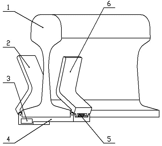
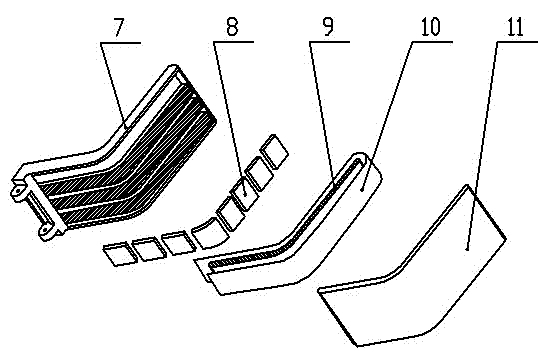
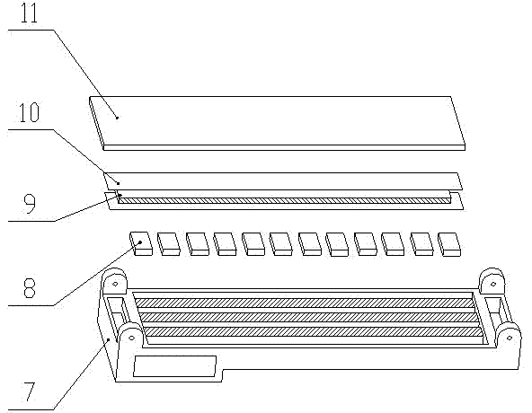
[0022] Such as figure 1 Shown, the present invention comprises bottom supporting plate 4, left side splint 2 and the right side splint 6 with the same structure, left side splint 2, right side splint 6 are respectively hinged on the both sides of bottom supporting plate 4, and bottom supporting plate 4 is installed on The lower surface of the rail bottom of the rail 1, the left splint 2 and the right splint 6 are respectively installed on both sides of the rail waist of the rail 1, and the left splint 2 and the right splint 6 are attached to the upper surface of the rail waist and the rail bottom of the rail 1 ;Such as figure 2 As shown, the left side clamping plate 2, the right side clamping plate 6 and the bottom supporting plate 4 all include a first support shell 7 and a second support shell 11, between the first support shell 7 and the second support shell 11 Four c...
PUM
 Abstract
Description
Claims
Application Information