Control method for polymer modification device

A control method and polymer technology, which is applied in the control field of polymer modification devices, can solve problems such as no system, reaction heat runaway, etc., and achieve the effect of preventing accidents and avoiding unplanned parking

Active Publication Date: 2020-09-29
CHINA PETROLEUM & CHEM CORP +1
View PDF3 Cites 0 Cited by
  • Summary
  • Abstract
  • Description
  • Claims
  • Application Information

AI Technical Summary

Problems solved by technology

In the process of processing, there is often the risk of dust explosion of polyvinyl alcohol raw materials, the risk of combustible gas explosion caused by volatilization or decomposition of low-boiling components contained in plasticizers and raw mat

Method used


Image

  • Control method for polymer modification device
  • Control method for polymer modification device
  • Control method for polymer modification device

Examples


Example Embodiment

[0071] Example 1

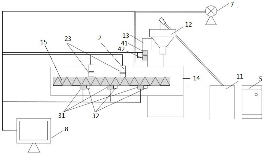
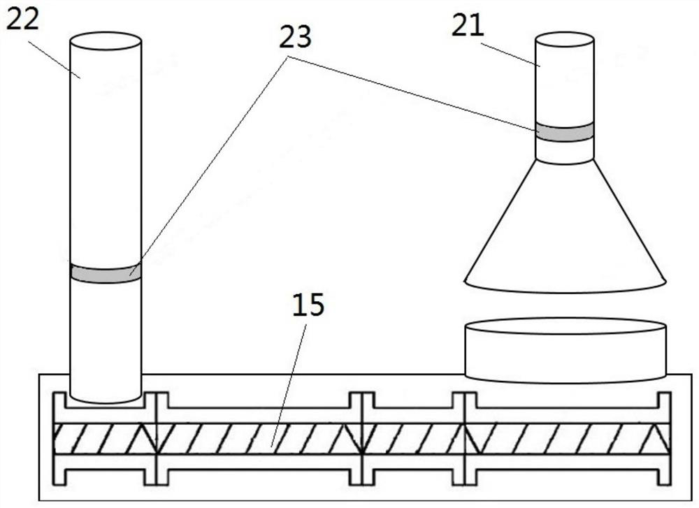
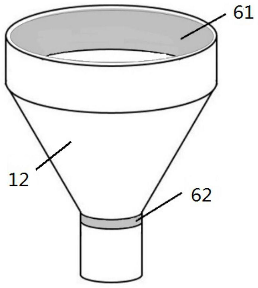
[0072] The polymer modification device includes an extrusion unit, a heating unit, a driving unit, a devolatilization unit, a control unit and an alarm structure. The extrusion unit includes a powder silo 11, a hopper 12, a plasticizer feed tank 13, a barrel 14 and a screw 15, on which a flow meter 41 and a flow alarm 42 are provided; The heating unit heats the barrel; the driving unit is a motor, and the output shaft of the motor is connected to the screw 15; the devolatilization unit includes a normal pressure devolatilizer 21 and a vacuum devolatilizer 22 arranged in sequence along the material movement direction, and a normal pressure devolatilizer The induced draft fan 7 connected to the tube 21 and the vacuum devolatilizer tube 22; the control unit is electrically connected to all the electronic control structures of the extrusion unit, the heating unit, the driving unit, the devolatilizer unit, the flow meter 41 and the flow alarm 42 respectively.

[0073...

Example Embodiment

[0075] Example 2

[0076] The polymer modification device includes an extrusion unit, a heating unit, a driving unit, a devolatilization unit, a control unit and an alarm structure. The extrusion unit includes a powder silo 11, a feeding hopper 12, a plasticizer feed tank 13, a barrel 14 and a screw 15. A plurality of temperature detectors 31 and 31 are arranged at even intervals along the material movement direction inside the barrel 14 The temperature alarm 32; the heating unit heats the barrel; the drive unit is a motor, and the output shaft of the motor is connected to the screw 15; the devolatilizer unit includes a normal pressure devolatilizer 21 and a vacuum devolatilizer 22 arranged in sequence along the material movement direction. The induced draft fan 7 connected to the normal pressure devolatilizer 21 and the vacuum devolatilizer 22; the control unit is respectively connected with all the electronic control structures of the extrusion unit, heating unit, drive unit, a...


PUM


Abstract

The invention relates to the technical field of safe control of polymer modification processes, and discloses a control method for a polymer modification device. The control method for the polymer modification device is characterized in that the polymer modification device comprises an extrusion unit, a driving unit, a heating unit, a devolatilization unit, a control unit and an alarm structure, wherein the extrusion unit comprises a barrel and a screw rod arranged inside the barrel. The control method comprises the following steps that raw materials and a plasticizer are added into the barrelrespectively; the heating unit heats the inside of the barrel; the driving unit drives the screw rod to rotate; and the devolatilization unit induces air into the barrel for devolatilization, whereinwhen the devolatilization air volume of the devolatilization unit is smaller than a preset air volume, the control unit controls the alarm structure to give an alarm. Through adoption of the controlmethod for the polymer modification device disclosed by the invention, accidents can be prevented effectively, and the whole polymer modification process is safe and effective.

Description

technical field [0001] The invention relates to the technical field of safety control of a polymer modification process, in particular to a control method of a polymer modification device for controlling parameters such as temperature, flow rate, and wind speed during the physical modification process of a polymer. Background technique [0002] As a polymer modification device, a screw extruder is commonly used, and the most commonly used is a twin-screw extruder. The twin-screw extruder is generally composed of a transmission device, a feeding device, a barrel, and a screw. It is used in conjunction with a granulation system and is widely used in the processing and molding of extruded products. Since the 1990s, screw extrusion has developed rapidly, integrating modification and molding processes, and is widely used in polymer grafting, crosslinking, block and other modification reactions. [0003] Among them, twin-screw extrusion technology can be used to modify the thermo...

Claims


Application Information

Patent Timeline
IPC IPC(8): B29C48/40B29C48/76B29C48/92B29C48/96B29C48/285B29B13/10B29K29/00
CPCB29C48/40B29C48/767B29C48/92B29C48/96B29C48/287B29C48/288B29B13/10B29C2948/92161B29C2948/924B29C2948/92476B29C2948/92209B29K2029/04B29C2948/92657B29C2948/92895B29C2948/92971B29C2948/92704
Inventor 孙冰金艳朱红伟姜杰文松赵磊
Owner CHINA PETROLEUM & CHEM CORP
Why Eureka
Try Eureka