Discharging control method and system for nose electrical precipitator for reducing air leakage rate of sintering system

A technology of electrostatic precipitator and control method, applied in power supply technology, electrostatic separation and other directions, can solve the problems of large air leakage rate of sintering system, fragile material level switch, unreliable material sealing method, etc.

Active Publication Date: 2014-04-09
ZHONGYE-CHANGTIAN INT ENG CO LTD
View PDF6 Cites 7 Cited by
  • Summary
  • Abstract
  • Description
  • Claims
  • Application Information

AI Technical Summary

Problems solved by technology

However, because the preset ash unloading sequence of the electrostatic precipitator at the head is usually determined by experience or factory settings, it cannot adapt to the actual dust removal conditions, resulting in the inability to achieve complete material sealing by relying on the preset ash unloading sequence
Since the material level switch is a vulnerable part, it is not reliable to rely on the material level switch to achieve material sealing, and the preset ash unloading sequence cannot adapt to the actual dust removal conditions, so it cannot accurately guide the as...

Method used


Image

  • Discharging control method and system for nose electrical precipitator for reducing air leakage rate of sintering system
  • Discharging control method and system for nose electrical precipitator for reducing air leakage rate of sintering system
  • Discharging control method and system for nose electrical precipitator for reducing air leakage rate of sintering system

Examples


Embodiment 1

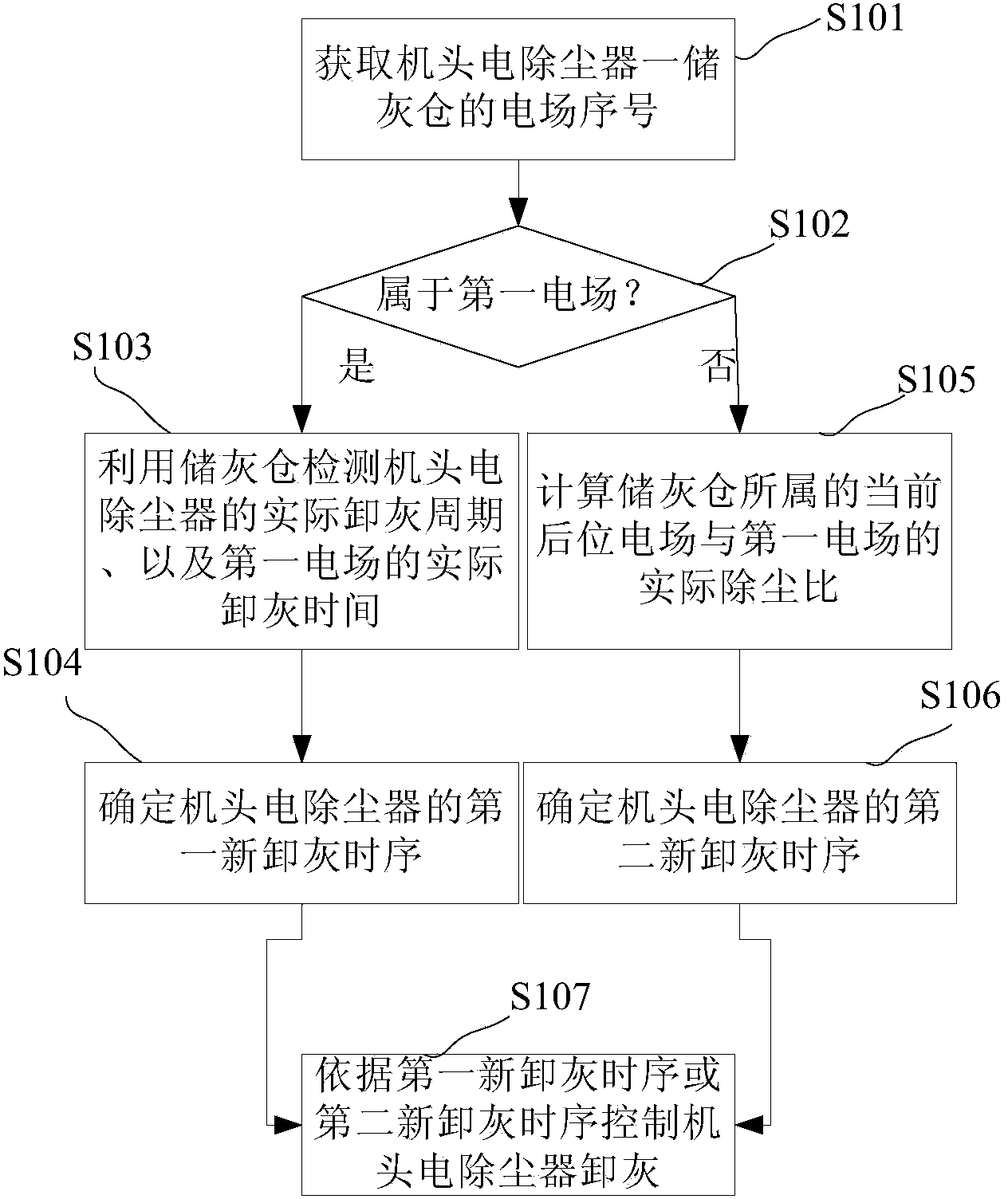
[0059] Please refer to the attached image 3 , image 3 It shows the flow of the control method for dust discharge of the head electrostatic precipitator for reducing the air leakage rate of the sintering system provided by Embodiment 1 of the present invention.

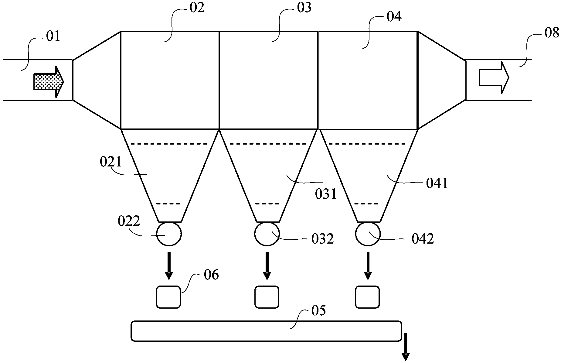
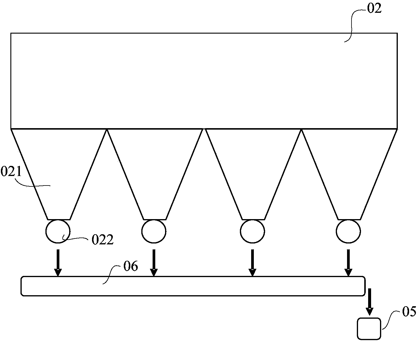
[0060] The head electrostatic precipitator in Embodiment 1 of the present invention includes a plurality of electric fields, and each electric field is provided with a plurality of ash storage bins, and each electric field has the same scale, and each electric field is provided with a plurality of ash storage bins, and each ash storage bin The bin is provided with a dust discharge valve. image 3 The process shown includes:

[0061] S101. Obtain the electric field serial number of the first ash storage bin of the electrostatic precipitator at the machine head.

[0062] The head electrostatic precipitator has multiple electric fields, and each electric field has multiple ash storage bins, and each ash storage bin h...

Embodiment 2

[0103] The second embodiment is improved on the basis of the first embodiment, how to determine the actual ash unloading period when the ash storage bin belongs to the first electric field.

[0104] Please refer to the attached Figure 4 , Figure 4 What is shown is the process of obtaining the actual ash unloading period of the head electrostatic precipitator provided by the second embodiment of the present invention.

[0105] Figure 4 The process shown includes:

[0106] S201. Empty the dust in the ash storage bin.

[0107] S202. Close the ash unloading valve of the ash storage bin after emptying.

[0108] S203. Detecting the first settling time for the dust in the ash storage bin to settle from an empty bin to a low material level.

[0109] S204. Detect the second settling time for the dust in the ash storage bin to settle from the empty bin to the high material level.

[0110] In steps S203 and S204, it is usually realized by detecting the time elapsed from the star...

Embodiment 3

[0119] Please refer to the attached Figure 5 , Figure 5 It shows the process of calculating the actual dust removal ratio between the current rear electric field and the first electric field to which the ash storage bin belongs according to the third embodiment of the present invention.

[0120] Figure 5 The process shown includes:

[0121] S301. Detect the third settling time for the dust in the ash storage bin to settle from an empty bin to a high material level.

[0122] In this step S301, the ash storage bin does not belong to the first electric field, but belongs to a subsequent electric field of the first electric field, that is, the current and subsequent electric field. As described in the above two embodiments, usually the detection of the third settling time is also realized by detecting the action of the material level switch.

[0123] S302. Calculate the actual dust removal ratio between the current rear electric field and the first electric field.

[0124]...


PUM


Abstract

The invention discloses a discharging control method for a nose electrical precipitator for reducing the air leakage rate of a sintering system. The method comprises the following steps: acquiring an electric field sequence number of an ash storage bin of the nose electrical precipitator; judging whether the ash storage bin belongs to a first electric field; detecting the actual discharging period of the nose electrical precipitator and the actual discharging time of the first electric field by using the ash storage bin when the ash storage bin belongs to the first electric field; determining a first new discharging time sequence of the nose electrical precipitator; calculating the actual discharging ratio of current post electric field of the ash storage bin to the first electric field when the ash storage bin does not belong to the first electric field; determining a second new discharging time sequence of the nose electrical precipitator; and controlling the nose electrical precipitator to discharge by adopting a gradual discharging mode of a discharge valve in each electric field according to the first new discharging time sequence or the second new discharging time sequence. The invention also provides a discharging control system for the nose electrical precipitator for reducing the air leakage rate of the sintering system. By adopting the method and the system, the air leakage rate of the overall sintering system can be reduced.

Description

technical field [0001] The invention relates to the technical field of dust removal for sintering systems, and more specifically, relates to a control method and system for dust discharge control of an electric precipitator at the head of a sintering system for reducing the air leakage rate of the sintering system. Background technique [0002] The head electrostatic precipitator of the sintering system is an important process and environmental protection equipment in the sintering process. During the sintering production process, the dust-laden flue gas in the large flue can only be discharged into the atmosphere after being treated by the head electrostatic precipitator of the sintering system. The head electrostatic precipitator of a large sintering system is usually a multi-electric field precipitator, that is, it has a multi-electric field (such as three electric fields or four electric fields) structure [0003] Please refer to Figure 1-2 , the illustrated three-elec...

Claims


Application Information

Patent Timeline
IPC IPC(8): B03C3/68B03C3/88
Inventor 刘雁飞孙英
Owner ZHONGYE-CHANGTIAN INT ENG CO LTD
Why Eureka
Try Eureka