Electric tool push rod assembly

A technology of electric tools and push rods, which is applied in the field of electric tool push rod components, and can solve problems such as no devices

Inactive Publication Date: 2015-12-02
NINGBO HAILIAN ELECTRIC APPLIANCE
View PDF6 Cites 0 Cited by
  • Summary
  • Abstract
  • Description
  • Claims
  • Application Information

AI Technical Summary

Problems solved by technology

But it still has the following disadvantages, the cutter will rotate when it is used, although the push rod can resist the cutter to prevent the cutter from retracting in the electric tool, but there is no device at the rear end of the push rod to resist the push rod to prevent the push rod from being pushed. The rod retreats, and when changing the tool, it no longer touches the rear end of the push rod, so that the push rod can move backward

Method used


Image

  • Electric tool push rod assembly
  • Electric tool push rod assembly
  • Electric tool push rod assembly

Examples


Embodiment Construction

[0019] Below in conjunction with accompanying drawing and specific embodiment the present invention will be described in further detail:

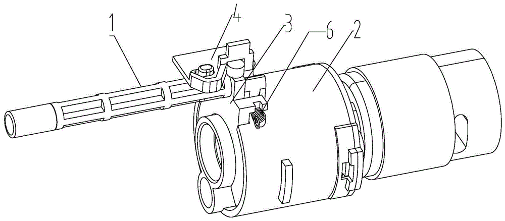
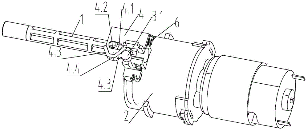
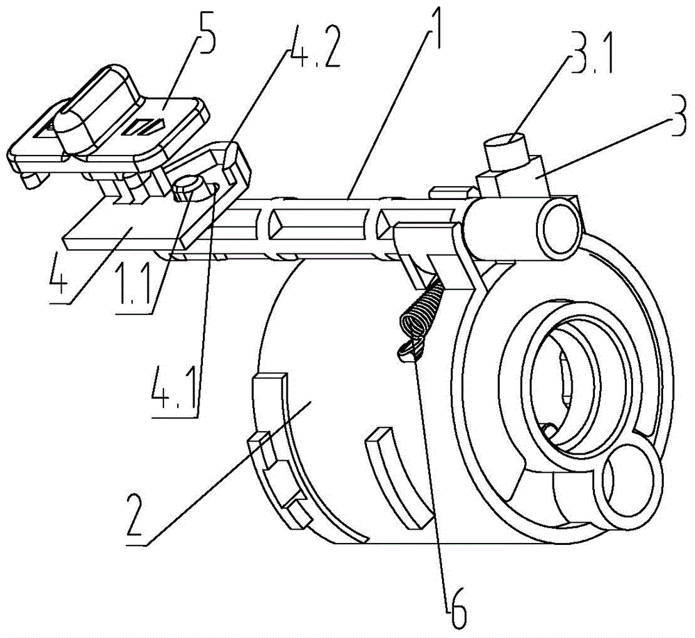
[0020] like figure 1 , 2 , 3, the present invention provides a power tool push rod assembly, which includes a push rod 1, the push rod 1 is used to push the tool down to the position of the tool chuck; the drive unit 2 is used to drive the tool chuck to rotate;

[0021] It also includes a push rod catch 3 that is rotatably connected to the drive unit 2, and the plane where its rotation track is located is perpendicular to the axis of the push rod 1. In this embodiment, the drive unit 2 includes a gearbox, and the push rod catch 3 Rotationally connected on the gearbox, the gearbox is a cylindrical structure, the axis of rotation of the push rod catch 3 is the same as the axis of the gearbox, and the push rod catch 3 is also provided with an elastic reset mechanism, which can be pushed in the natural state. The rod stopper 3 faces the push ...


PUM


Abstract

The invention provides an electric tool push rod assembly. The electric tool push rod assembly comprises a push rod and a driving unit and further comprises a push rod stop piece, wherein the push rod stop piece is rotatably connected to the driving unit and the plane where the rotating track is located is perpendicular to the axis of the push rod. An elastic reset mechanism is further arranged on the push rod stop piece. A push rod connection piece and a push rod button are further arranged on the push rod. A first protrusion is arranged on the push rod. A long hole is formed in the push rod connection piece. A cylindrical second protrusion is arranged at the top end of the push rod stop piece. A third protrusion which can abut against the second protrusion when moving in order to ensure that the push rod stop piece rotates is arranged on the push rod connection piece. Due to the adoption of the structure, the rear end of the push rod can be propped up when an electric tool works and the push rod can move freely when being moved backwards.

Description

technical field [0001] The invention relates to an electric tool push rod assembly used in a hand-held electric tool with a drum-type tool magazine that can be rotated for tool replacement. Background technique [0002] The Chinese patent application whose publication number is CN101563192 discloses an electric tool with a drum type tool magazine. The electric tool has a pistol-shaped casing, and has a main axis extending in the direction of the gun barrel, and the output shaft of the electric tool is at the exit of the barrel direction, which is a tool chuck, and the casing is equipped with a motor, a drum tool magazine and The transmission device, the drum-type tool magazine is a cylindrical structure, the axis of the drum-type tool magazine and the axis of the tool chuck are parallel to the main axis, and the drum-type tool magazine is equipped with a tool chamber parallel to the main axis in a ring on itself. Depending on the rotational position of the drum magazine, re...

Claims


Application Information

Patent Timeline
Patent Type & Authority Patents(China)
IPC IPC(8): B25F5/00B25F3/00
Inventor 黄永林王卫
Owner NINGBO HAILIAN ELECTRIC APPLIANCE
Why Eureka
Try Eureka