Belt conveyor headstock and manufacturing method thereof

A head frame and belt conveyor technology, applied in the field of conveyor racks, can solve problems affecting work progress, reducing work efficiency, affecting transportation efficiency, etc., to achieve the effects of ensuring transmission efficiency, improving work efficiency, and avoiding belt deviation

Active Publication Date: 2014-04-09
GUIZHOU HONGSHI COAL MACHINE MFG
View PDF4 Cites 0 Cited by
  • Summary
  • Abstract
  • Description
  • Claims
  • Application Information

AI Technical Summary

Problems solved by technology

[0002] The side plate of the head frame of the side plate belt conveyor is divided into left and right side plates such as figure 2 , image 3 As shown, two drive rollers are installed between the two side plates. The drive rollers pass through the sleeves on the two side plates. One side is equipped with a reducer to form a transmission part, and the other side is installed with a large gear. The two gears mesh with each other to achieve the two main rollers. Synchronous operation improves the transportation efficiency of the belt conveyor; if the coaxiality of the two main rollers is not high, not only will the transportation efficiency not be improved, but it will cause the belt of the belt conveyor to deviate, and the large gears cannot be meshed correctly, which will affect the synchronous rotation, and then Affect work progress and reduce work efficiency
[0003] However, in the prior art, the preparation method used for the side plate of the head frame of the side plate type belt conveyor is difficult to meet the coaxiality of the main drum, which leads to the deviation of the belt of the belt conveyor, which affects the transportation efficiency and reduces the work efficiency. efficiency

Method used


Image

  • Belt conveyor headstock and manufacturing method thereof
  • Belt conveyor headstock and manufacturing method thereof
  • Belt conveyor headstock and manufacturing method thereof

Examples


Embodiment 1

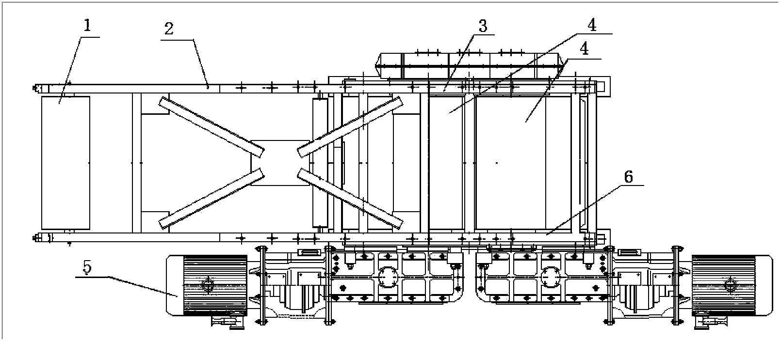
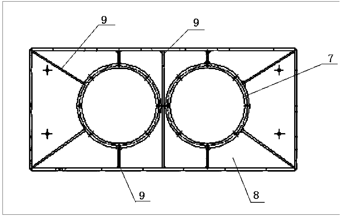
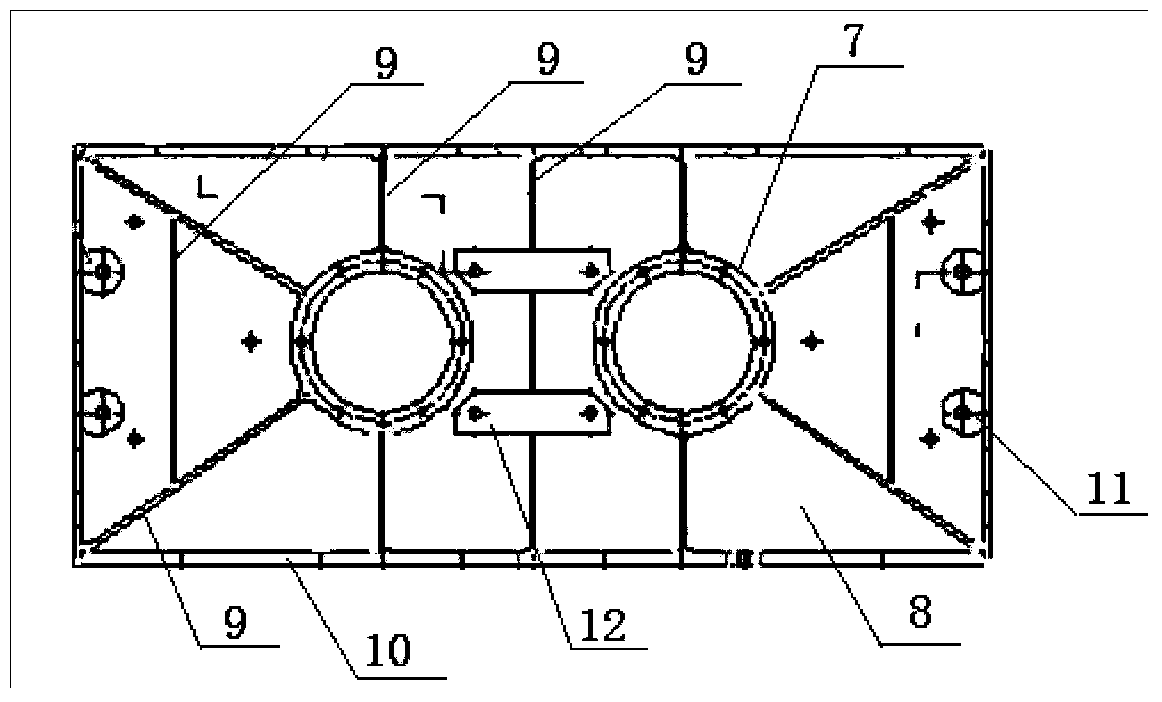
[0018] Such as figure 1 , figure 2 , image 3 and Figure 4 As shown, a belt conveyor head frame includes an extension frame 2, an unloading drum 1 arranged at the front end of the extension frame 2, and a left side plate 6 and a right side plate are respectively arranged on the left and right sides of the rear end of the extension frame 2. The side plate 3 is provided with a transmission part 5 on the side of the left side plate 6; The reducer block 12 is composed of; the right side plate 3 is composed of the sleeve 7, the rib plate 9 and the side plate 10 arranged on the side plate 8, and it is characterized in that: the sleeve 7 on the left side plate 6 and the right side plate The center distance of the upper sleeve 7 is consistent, which ensures the coaxiality of the main drum, ensures that the large gears can be meshed correctly, and improves work efficiency.

Embodiment 2

[0020] Such as figure 1 , figure 2 , image 3 and Figure 4 As shown, a method for preparing the head frame of a belt conveyor uses tooling to install the left side plate and the right side plate. Specifically, when installing the left side panel, first use tooling to insert the sleeve on the left side panel on the small circle, and determine the position and center distance of the sleeve before installing the left side panel other boards on the right side board; when installing the right side board, first use tooling to set the sleeve on the right side board on the big circle, and after confirming the position and center distance of the sleeve, install other boards on the right side board In this way, the left and right side plates processed on the same tooling can effectively ensure the position and center distance of the sleeve. After installing the main drive pulley, the coaxiality of the main pulley can also be guaranteed to ensure transmission efficiency and prevent ...

Embodiment 3

[0022] Such as figure 1 , figure 2 , image 3 or Figure 4 As shown, the side plate of the head frame of the side plate belt conveyor is divided into left and right side plates, and two driving rollers are installed between the two side plates. The driving rollers pass through the sleeves on both sides of the plate. , the two gears mesh with each other to achieve the synchronous operation of the two main rollers and improve the transportation efficiency; if the coaxiality of the two main rollers is not high, it will cause the belt conveyor belt to deviate, and the large gears cannot be meshed correctly, which will affect the synchronous rotation , therefore, in order to ensure the coaxiality of the two main rollers and the correct meshing of the large gears, the position and center distance of the sleeves on the left and right side plates must be ensured. Therefore, the technical solution of the present invention adopts tooling to weld the left and right side plates , effe...


PUM


Abstract

The invention relates to the technical field of conveyor racks, in particular to a belt conveyor headstock and a manufacturing method of the belt conveyor headstock. A left side plate and a right side plate on the belt conveyor headstock are machined by the adoption of the same tool, in this way, positions and center distances of sleeves are effectively ensured, so that the center distance of the sleeve on the left side plate is in accordance with the center distance of the sleeve on the right side plate, then the coaxiality of main rollers is ensured when the main transmission rollers are installed, the transmission efficiency is ensured, belt off tracking is avoided, and working efficiency is improved.

Description

technical field [0001] The invention relates to the technical field of conveyor frames, in particular to a belt conveyor head frame and a preparation method thereof. Background technique [0002] The side plate of the head frame of the side plate belt conveyor is divided into left and right side plates such as figure 2 , image 3 As shown, two drive rollers are installed between the two side plates. The drive rollers pass through the sleeves on the two side plates. One side is equipped with a reducer to form a transmission part, and the other side is installed with a large gear. The two gears mesh with each other to achieve the two main rollers. Synchronous operation improves the transport efficiency of the belt conveyor; if the coaxiality of the two main rollers is not high, not only will it not improve the transport efficiency, but it will cause the belt of the belt conveyor to deviate, and the large gears will not mesh correctly, which will affect the synchronous rotatio...

Claims


Application Information

Patent Timeline
Patent Type & Authority Applications(China)
IPC IPC(8): B65G21/00
Inventor 张平丁红平陈贵琴杨长江黄元李康王建华胡成梅周仕远
Owner GUIZHOU HONGSHI COAL MACHINE MFG
Why Eureka
Try Eureka