
A new type of exhaust heating device for photovoltaic glass production

A photovoltaic glass and heating device technology, applied in glass furnace equipment, glass manufacturing equipment, manufacturing tools, etc., can solve the problem of inability to achieve rapid melting of gate plate solidified glass, inability to adjust horizontal spacing simultaneously, and uneven flame intensity, etc. problems, to shorten the time for replacing lip bricks and calenders, achieve good results, and improve the success rate.

Active Publication Date: 2015-10-28
CAIHONG GRP ELECTRONICS CO LTD
View PDF3 Cites 1 Cited by
  • Summary
  • Abstract
  • Description
  • Claims
  • Application Information

AI Technical Summary

Problems solved by technology

The currently widely used exhaust heating device has the following disadvantages: 1. The shape of the heating nozzle is mostly cylindrical, and the flame intensity is uneven; 2. The exhaust heating gun does not use a chain suspension device, which is inconvenient to erect; 3. The exhaust heating The angle of the gun flame, the vertical height and the horizontal distance from the gate plate cannot be adjusted at the same time, and the rapid melting of the solidified glass at the outer edge of the lower end of the gate plate and its surroundings cannot be realized.

Method used


Image

  • A new type of exhaust heating device for photovoltaic glass production
  • A new type of exhaust heating device for photovoltaic glass production
  • A new type of exhaust heating device for photovoltaic glass production

Examples


Embodiment Construction

[0014] The present invention will be described in further detail below in conjunction with the accompanying drawings.

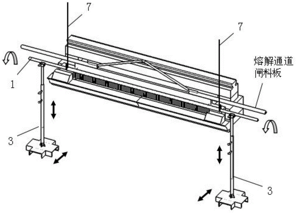
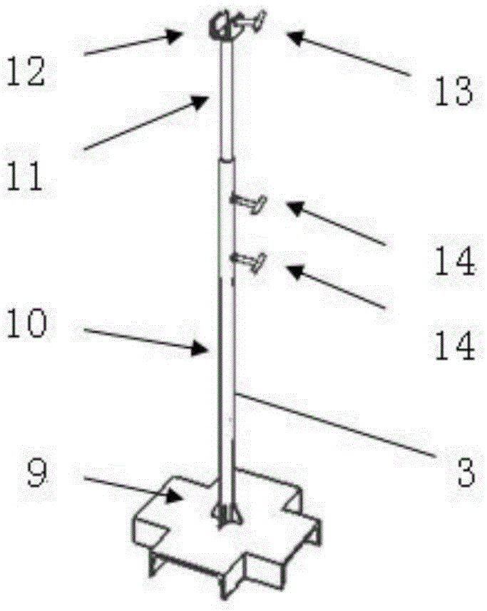
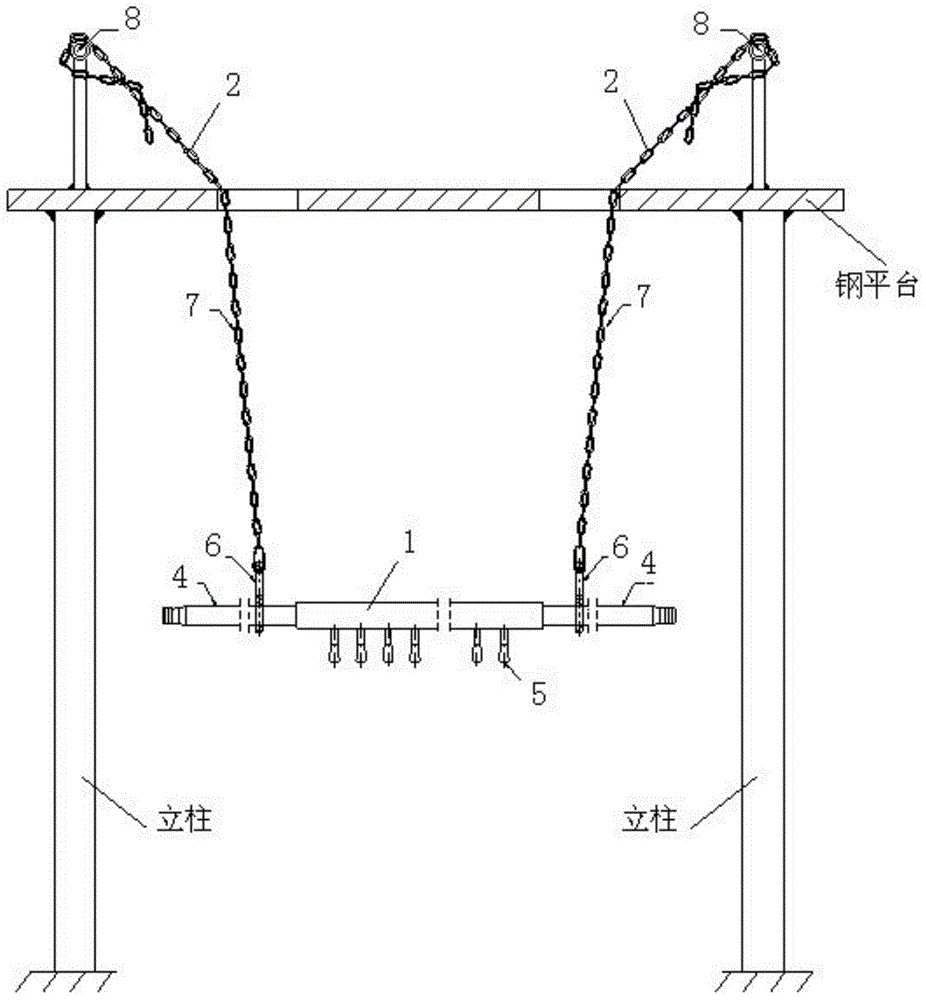
[0015] See attached figure 1 , 2 , 3, a new type of photovoltaic glass production exhaust heating device, including exhaust heat gun 1, suspension device 2 and support 3; exhaust heat gun 1 includes connecting rod 4, and connecting rod 4 is evenly arranged with nozzles in a straight line 5. The connecting rod 4 is connected with the suspension chain 7 of the suspension device 2 through the chain connector 6; the suspension device 2 includes a suspension chain 7 and a special beam 8; the bracket 3 includes a movable base 9, and the movable base 9. The center is fixedly welded with a fixed rod 10. The top of the fixed rod 10 is provided with a movable rod 11. The movable rod 11 can be telescopically moved in the fixed rod 10 to adjust the height of the exhaust heat gun 1 up and down. 14 is locked and fixed, and the top of the movable rod 11 is provided with a...


PUM


Abstract

Provided is a novel fire discharging and heating device for photovoltaic glass production. The fire discharging and heating device is mainly composed of a fire discharging and heating gun, suspension devices and supports. The fire discharging and heating gun comprises connecting rods, burners and chain connecting pieces. Each suspension device comprises a suspension chain and a special crossbeam. Each support comprises a movable pedestal, a fixed rod, a movable rod, a first locking top thread, a clamping device and a second locking top thread. When the fire discharging and heating gun is used, the fire discharging and heating gun is placed to an appropriate height downward vertically through the suspension chains. When the supports are used, the supports are arranged under the connecting rods of the fire discharging and heating gun, and one support is arranged on the left and one support is arranged on the right. The connecting rods of the fire discharging and heating gun are fixed in U-shaped slots of the U-shaped clamping devices of the supports. the height of the fire discharging and heating gun is adjusted up and down through telescopic movement of the movable rods in the fixed rods. The burners of the fire discharging and heating gun are subjected to any angular adjustment through the U-shaped clamping devices of the supports, and the uniformity of flame intensity can be raised. Rapid erection and remove of the fire discharging and heating device are achieved, and the fire discharging and heating device has advantages of simple structure, convenient usage and good effects.

Description

technical field [0001] The invention relates to the technical field of solar photovoltaic glass production, in particular to a novel exhaust heating device for photovoltaic glass production. Background technique [0002] At present, in the production of solar photovoltaic glass in my country, when replacing lip bricks and calenders, it is necessary to use a gate plate to block the glass liquid flowing out of the melting channel. After the glass liquid is blocked, the glass liquid on the outer edge of the lower end of the gate plate is quickly cooled. To solidify, when re-leading the plate, it is necessary to lift the gate plate to a certain height. Before lifting the gate plate, use a fire heating device to heat and melt the solidified glass at the lower edge of the gate plate and its surroundings. The currently widely used exhaust heating device has the following disadvantages: 1. The shape of the heating nozzle is mostly cylindrical, and the flame intensity is uneven; 2. Th...

Claims


Application Information

Patent Timeline
Patent Type & Authority Patents(China)
IPC IPC(8): C03B5/16
Inventor 成建章吴文超
Owner CAIHONG GRP ELECTRONICS CO LTD
Learn More