Combined Bailey frame load-bearing bent frame for pouring long-span concrete beams

A concrete beam and combined technology, which is applied in construction, ship lifting devices, and machinery for lifting ships along slopes, etc., can solve the problems of high cost investment, slow construction progress, and difficulty in ensuring construction quality, and achieve strong safety and stability. Guaranteed construction quality, convenient and quick demolition effect

Active Publication Date: 2015-09-02
CHINA GEZHOUBA GROUP CO LTD
View PDF5 Cites 0 Cited by
  • Summary
  • Abstract
  • Description
  • Claims
  • Application Information

AI Technical Summary

Problems solved by technology

[0002] In the construction of ship lifts in hydropower stations, it is common to encounter cast-in-place concrete beams and slab structures designed on two adjacent concrete vertical walls, such as top beams and platforms of ship lifts (such as figure 1 ), this kind of structural concrete usually has the characteristics of large span, heavy weight, etc., and the height from the ground is also large. It is a big safety hazard, and it is very difficult to set up and dismantle the bent racks, and at the same time, it needs to consume a lot of materials, resulting in high cost investment, slow construction progress, and difficulty in ensuring construction quality.

Method used


Image

  • Combined Bailey frame load-bearing bent frame for pouring long-span concrete beams
  • Combined Bailey frame load-bearing bent frame for pouring long-span concrete beams
  • Combined Bailey frame load-bearing bent frame for pouring long-span concrete beams

Examples


Embodiment Construction

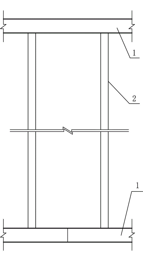
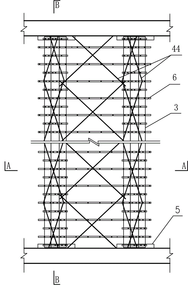
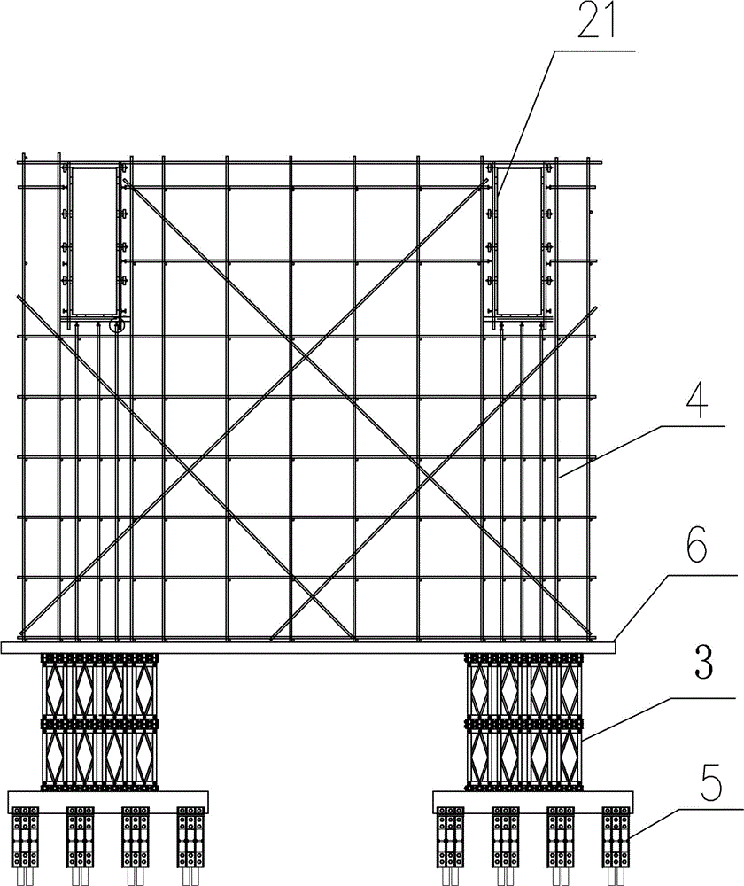
[0018] Such as Figure 2-6 As shown, a combined Bailey frame load-bearing bent frame for pouring large-span concrete beams, including a combined Bailey frame beam 3, a steel pipe bent frame 4, a support system 5, and at least two combined Bailey frames parallel to each other The two ends of the beam 3 are respectively located on the steel box girder 52 of the support system 5 fixed on two parallel concrete upright walls 1, and the combined Bailey frame beam 3 is uniformly and vertically arranged with multiple beams of different lengths. 1. I-beam bases 6 parallel to each other, steel pipe bent frames 4 are set up on the I-beam bases 6 .

[0019] The support system 5 is composed of a plurality of load-bearing steel corbels 51 and steel box girders 52, the load-bearing steel corbels 51 are fixedly connected with a plurality of pre-embedded anchor cones 53 arranged on the concrete upright wall 1, and the steel box girder 52 Erection on the top surface of load-bearing steel corbe...


PUM


Abstract

Disclosed is a combined type bailey frame load-bearing shelving used for pouring a large-span concrete beam. The combined type bailey frame load-bearing shelving comprises combined type bailey frame beams, a steel pipe shelving and supporting base systems. The two ends of each of the bailey frame beams are respectively arranged on a steel box beam. The steel box beams are fixed on the two parallel supporting base systems of a concrete erect wall body. A plurality of I-shaped parallel steel bases are arranged on the bailey frame beams. The steel pipe shelving is arranged on the steel bases in a lapping mode. Concrete beam moldboards are arranged on the upper portion of the steel pipe shelving. A plurality of steel corbels fixed on the concrete wall surfaces at two sides are used to support the combined type bailey frame load-bearing shelving. Shortages of a conventional construction method that falling shelving erecting moldboards are set up normally are overcome. The combined type bailey frame load-bearing shelving is large in load-bearing amount and high in safety and stability. Bearing requirements of an upper air beam and construction of plate concrete are guaranteed. The combined type bailey frame load-bearing shelving is convenient and quick to erect and dismantle, and is capable of saving the engineering cost, accelerating a construction schedule and guaranteeing the construction quality. The combined type bailey frame load-bearing shelving is particularly suitable for a working condition of pouring a concrete beam and a plate structure.

Description

technical field [0001] The invention relates to the technical field of steel structures, in particular to a combined Bailey frame load-bearing bending device for pouring large-span concrete beams. Background technique [0002] In the construction of ship lifts in hydropower stations, it is common to encounter cast-in-place concrete beams and slab structures designed on two adjacent concrete vertical walls, such as top beams and platforms of ship lifts (such as figure 1 ), this kind of structural concrete usually has the characteristics of large span, heavy weight, etc., and the height from the ground is also large. It is a big safety hazard, and it is very difficult to set up and dismantle the bent racks. At the same time, it needs to consume a lot of materials, resulting in high cost investment, slow construction progress, and difficulty in ensuring construction quality. Contents of the invention [0003] The technical problem to be solved by the present invention is to ...

Claims


Application Information

Patent Timeline
Patent Type & Authority Patents(China)
IPC IPC(8): E02C3/00E02C5/00E02D15/02
Inventor 詹剑霞汪文亮朱俊杰杨志书李士华
Owner CHINA GEZHOUBA GROUP CO LTD
Why Eureka
Try Eureka