Part distribution device of automatic assembling device

A technology of automatic assembly and shunt device, which is applied in metal processing equipment, metal processing, manufacturing tools, etc., can solve the problems of low shunt efficiency and complex structure, and achieve the effect of high shunt efficiency and simple and compact structure.

Inactive Publication Date: 2014-04-16
HONGSHENG MACHINERY EQUIP
View PDF9 Cites 10 Cited by
  • Summary
  • Abstract
  • Description
  • Claims
  • Application Information

AI Technical Summary

Problems solved by technology

The disadvantages of the existing part diverting device of automatic assembly equipment are: the structure is relatively complicated, and it can only divert the workpieces on one feeding track, and the diverting efficiency is low

Method used


Image

  • Part distribution device of automatic assembling device
  • Part distribution device of automatic assembling device
  • Part distribution device of automatic assembling device

Examples


Embodiment 1

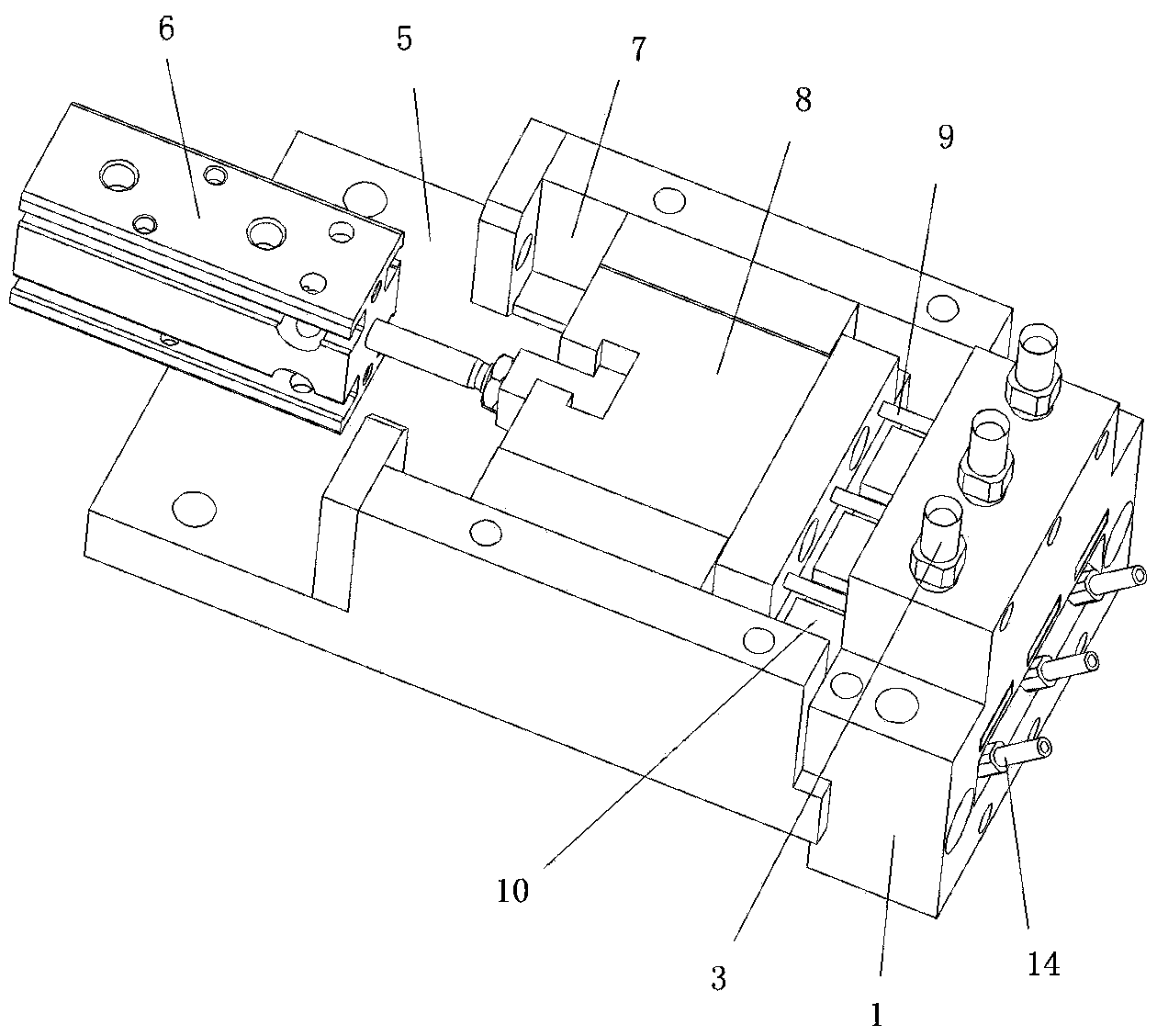
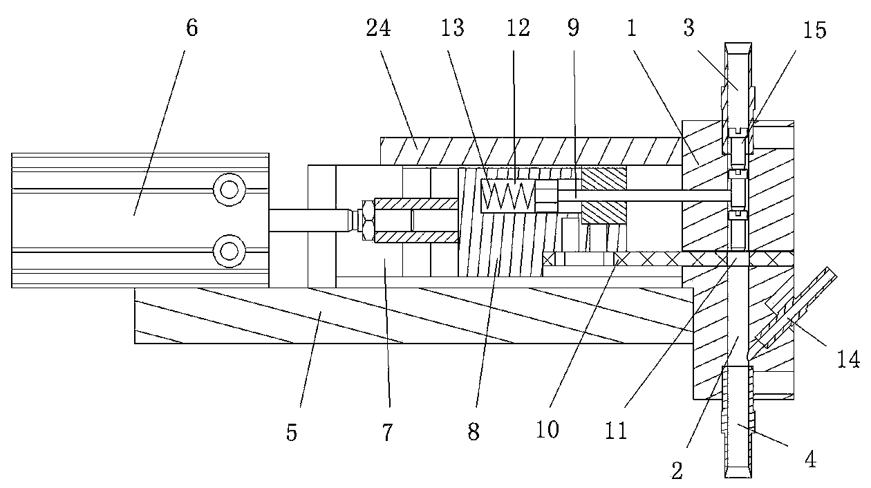
[0019] refer to figure 1 , figure 2 , a parts distribution device for automatic assembly equipment, comprising a base body 1, a plurality of distribution channels 2 are arranged in the base body 1, and the entrance of each distribution channel 2 is connected with a feed pipe 3, and each channel The outlets of the distribution channels 2 are all connected to a discharge pipe 4, and there is an angle between the axis of each distribution channel 2 and the horizontal line, and the side walls of each distribution channel 2 are arranged from top to bottom. The upper intercepting piece and the lower intercepting piece are arranged side by side, and the distance between the upper intercepting piece and the lower intercepting piece is a workpiece distance. in the distribution channel 2.

[0020] The interception driving mechanism includes a support 5 fixed on the base 1 and an interception cylinder 6 fixed on the support 5, the support 5 is provided with a chute 7, and the chute 7 ...

Embodiment 2

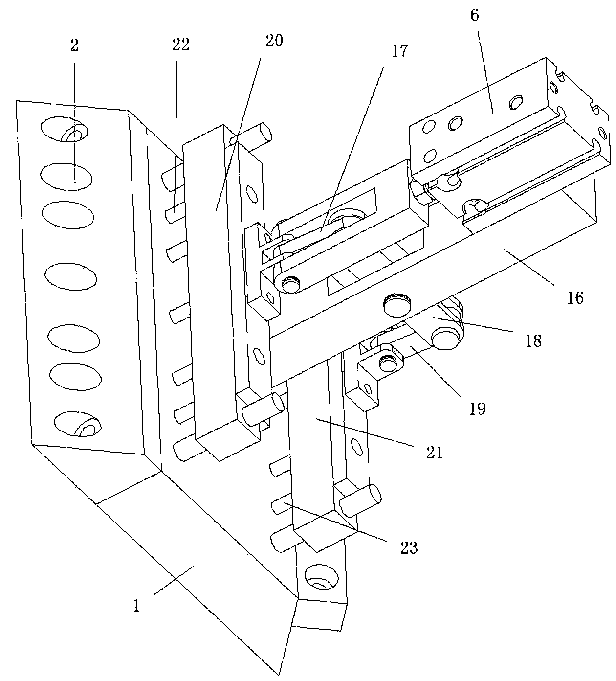
[0027] refer to image 3 , Figure 4 , a parts distribution device for automatic assembly equipment, comprising a base body 1, a plurality of distribution channels 2 are arranged in the base body 1, and the entrance of each distribution channel 2 is connected with a feed pipe 3, and each channel The outlets of the distribution channels 2 are all connected to a discharge pipe 4, and there is an angle between the axis of each distribution channel 2 and the horizontal line, and the side walls of each distribution channel 2 are arranged from top to bottom. The upper intercepting piece and the lower intercepting piece are arranged side by side, and the distance between the upper intercepting piece and the lower intercepting piece is a workpiece distance. in the distribution channel 2.

[0028] The intercepting drive mechanism includes a bracket 16 fixed on the base 1 and an intercepting cylinder 6 fixed on the bracket 16, and also includes an upper connecting rod 17, a middle con...


PUM


Abstract

The invention discloses a part distribution device of an automatic assembling device. The part distribution device comprises a base body, a plurality of distribution channels are formed in the base body, an inlet of each distribution channel is connected with a feeding pipe, an outlet of each distribution channel is connected with a discharging pipe, an included angle is formed between the axis of each distribution channel and the horizontal line, and an upper blocking part and a lower blocking part are arranged on the side wall of each distribution channel side by side from top to bottom, wherein the distance between the upper blocking part and the lower blocking part is equal to the length of a workpiece, and the upper blocking part and the lower blocking part are driven by a blocking driving mechanism to be blocked in the distribution channel in a mutually-staggered mode. The part distribution device has the advantages that due to the facts that the structure is adopted, and the upper blocking parts and the lower blocking parts are blocked in the distribution channels in the mutually-staggered mode, distribution of workpieces is achieved, and the device is simple and compact in structure and high in distribution efficiency.

Description

technical field [0001] The invention relates to a part flow device for automatic assembly equipment. Background technique [0002] In the prior art, long workpieces such as screws, screw rods, pin shafts, and springs are usually lined up and transported forward through the feeding mechanism during automatic assembly, and assembled at the assembly position, but these workpieces are all one by one. Moving forward along the feeding track one by one, a parts diverter device of the automatic assembly equipment is required to intercept, so that a certain distance between the previous workpiece and the subsequent workpiece at the assembly position is required for assembly. The disadvantages of the existing parts diverting device of automatic assembly equipment are: the structure is relatively complicated, and the diversion can only be performed on the workpieces on one feeding track, and the diversion efficiency is low. Contents of the invention [0003] In order to overcome the...

Claims


Application Information

Patent Timeline
Patent Type & Authority Applications(China)
IPC IPC(8): B23P19/00
CPCB23P19/003
Inventor 吴兴钿
Owner HONGSHENG MACHINERY EQUIP
Why Eureka
Try Eureka