Backflow type conveying device with flow dividing and flow combining functions and conveying technology

A conveying device and function technology, which is applied in the field of return conveying device and conveying process, can solve the problems of wear of jig and synchronous belt, affecting the service life, and requiring repeated assembly or production.

Active Publication Date: 2018-11-06
东莞市宏先自动化设备有限公司
View PDF5 Cites 9 Cited by
  • Summary
  • Abstract
  • Description
  • Claims
  • Application Information

AI Technical Summary

Problems solved by technology

For the automatic production and assembly of electronic products, the above-mentioned 2nd and 3rd methods are often used as the means of transmission of spare parts of electronic products; in the actual production process, there are still the following technical difficulties to be solved for the 3rd material transmission method: (1) During actual production, the timing belt generally keeps working continuously, that is, it moves forward in a straight line, and the jig needs to stop when it is driven forward by the static friction of the timing belt to the processing / assembly station, so that the material can be processed or Assembly, at this time, the static friction between the bottom of the jig and the synchronous belt that continues to move is converted into dynamic friction, and wear occurs between the jig and the synchronous belt, which affects the service life; (2) In the actual production process, a single processing station It is often necessary to complete the processing or assembly of two or more materials, so it is required to transmit two or more fixtures synchronously on the single guide rail, which requires the transmission device to have the function of simultaneously transmitting two or more fixtures. For versatility, the transfer device also needs to be able to switch between a single jig and two or more jigs during transmission, so as to realize the confluence and diversion of the jigs; (3), in the actual production process, it may be necessary to repeat production or assemble multiple jigs. In the case of a single material, or when a single part of the material needs to be assembled or produced repeatedly, it is required that the jig can be transmitted multiple times on a single guide rail so that the material can be transported to the processing station of a single guide rail multiple times.

Method used


Image

  • Backflow type conveying device with flow dividing and flow combining functions and conveying technology
  • Backflow type conveying device with flow dividing and flow combining functions and conveying technology
  • Backflow type conveying device with flow dividing and flow combining functions and conveying technology

Examples


Embodiment Construction

[0058] The present invention will be further described below in conjunction with accompanying drawing:

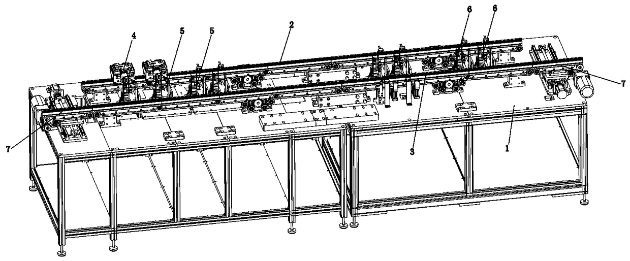
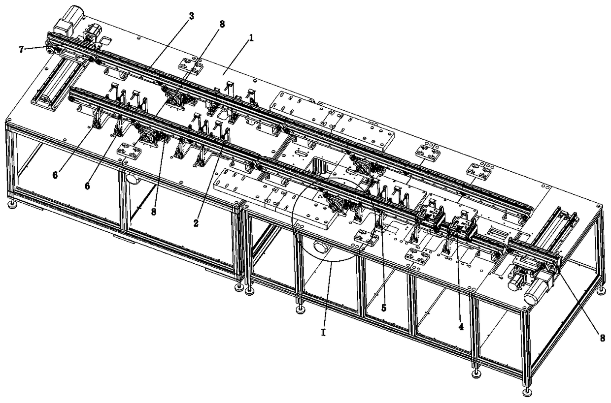
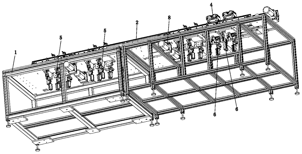
[0059] Such as Figure 1 to Figure 21 As shown, the technical solution adopted by the present invention is as follows: a return flow conveying device with the functions of diversion and confluence, including a processing line 2, a return line 3, a carrying device 4, a double blocking and positioning mechanism 5, and a single blocking and positioning mechanism 6. The transfer mechanism 7 and the transmission mechanism 8, wherein the above-mentioned processing line 2 and return line 3 are arranged on the frame 1 in parallel and at intervals, and the processing line 2 and the return line 3 are respectively provided with a single Guide rail 86, the both sides of single guide rail 86 are respectively provided with the conveyer belt 85 that extends in the same direction with single guide rail 86; Above-mentioned transmission mechanism 8 comprises two sets, and two transmission me...


PUM


Abstract

The invention discloses a backflow type conveying device with flow dividing and flow combining functions and a conveying technology thereof. The device comprises a machining line, a backflow line, a carrying device, a blocking and positioning mechanism, a transferring mechanism and a transmission mechanism. The machining line and the backflow line are each provided with a single guide rail extending in the linear line direction, the carrying device is arranged on the single guide rail of the machining line or backflow line, the dual-blocking and positioning mechanism or the single-blocking positioning and blocking mechanism is arranged on the machining line, the carrying device is blocked by a blocking assembly of the blocking and positioning mechanism and then is lifted upwards, the carrying device is blocked and lifted and then is positioned through a positioning assembly of the blocking and positioning mechanism, and the transferring mechanism is arranged between the machining lineand the backflow line and enables the carrying device to move between the machining line and the backflow line. The jig blocking lifted function is achieved, flow dividing and combining conversion isachieved, a closed jig backflow path is formed, the wear is effectively reduced, use is flexible, and generality is high.

Description

technical field [0001] The invention relates to the field of mechanical automation, in particular to a backflow conveying device and a conveying process with functions of diversion and confluence. Background technique [0002] The transportation of processed products, spare parts, etc. is an essential basic process in the field of mechanical automation. Its main function is to automatically transfer products, spare parts, etc. to processing and assembly stations, and to position them so that products and spare parts can be processed , assembly and other processes; after the processing and assembly are completed, it needs to be automatically released and positioned so that subsequent products can enter; the structural components used for transportation functions in the prior art include: 1. Conveyor belts, timing belts, chains, etc. as direct bearing carriers Drive the material to move, this kind of material transmission method is suitable for occasions that require low mater...

Claims


Application Information

Patent Timeline
Patent Type & Authority Applications(China)
IPC IPC(8): B65G47/88B65G37/02B65G47/68B65G47/71
CPCB65G37/02B65G47/681B65G47/71B65G47/8815B65G47/8876
Inventor 劳世敏
Owner 东莞市宏先自动化设备有限公司
Why Eureka
Try Eureka