High precison femtosecond laser synchronous technology and device

A femtosecond laser and synchronization device technology, applied in lasers, laser parts, phonon exciters, etc., can solve the problem of low synchronization accuracy, and achieve narrow pulse width, high synchronization accuracy, stability and synchronization reliability. Enhanced effect

Inactive Publication Date: 2006-11-08
INST OF PHYSICS - CHINESE ACAD OF SCI
View PDF0 Cites 0 Cited by
  • Summary
  • Abstract
  • Description
  • Claims
  • Application Information

AI Technical Summary

Problems solved by technology

[0004] At present, the products and devices that can be used as commercial synchronous femtosecond lasers all adopt the active synchronization method. As mentioned above, this technology mainly relies on the use of a circuit feedback system outside the oscillator cavity to stabilize the length of the two laser cavities to realize the synchronization between the oscillators. Synchronous locking, but its synchronization accuracy is usually one to two orders of magnitude lower than passive synchronization

Method used


Image

  • High precison femtosecond laser synchronous technology and device
  • High precison femtosecond laser synchronous technology and device
  • High precison femtosecond laser synchronous technology and device

Examples


Embodiment 1

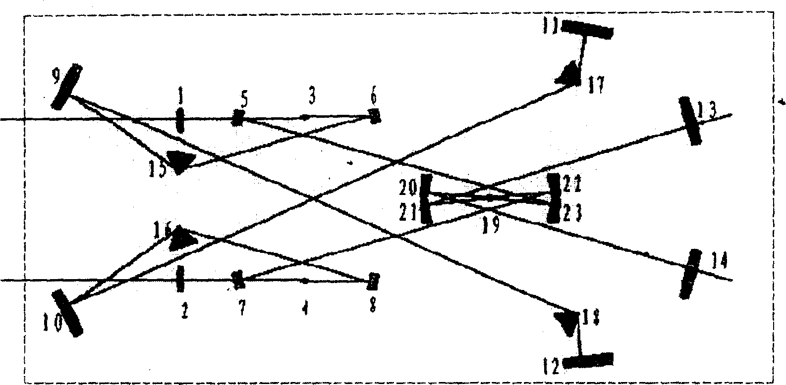
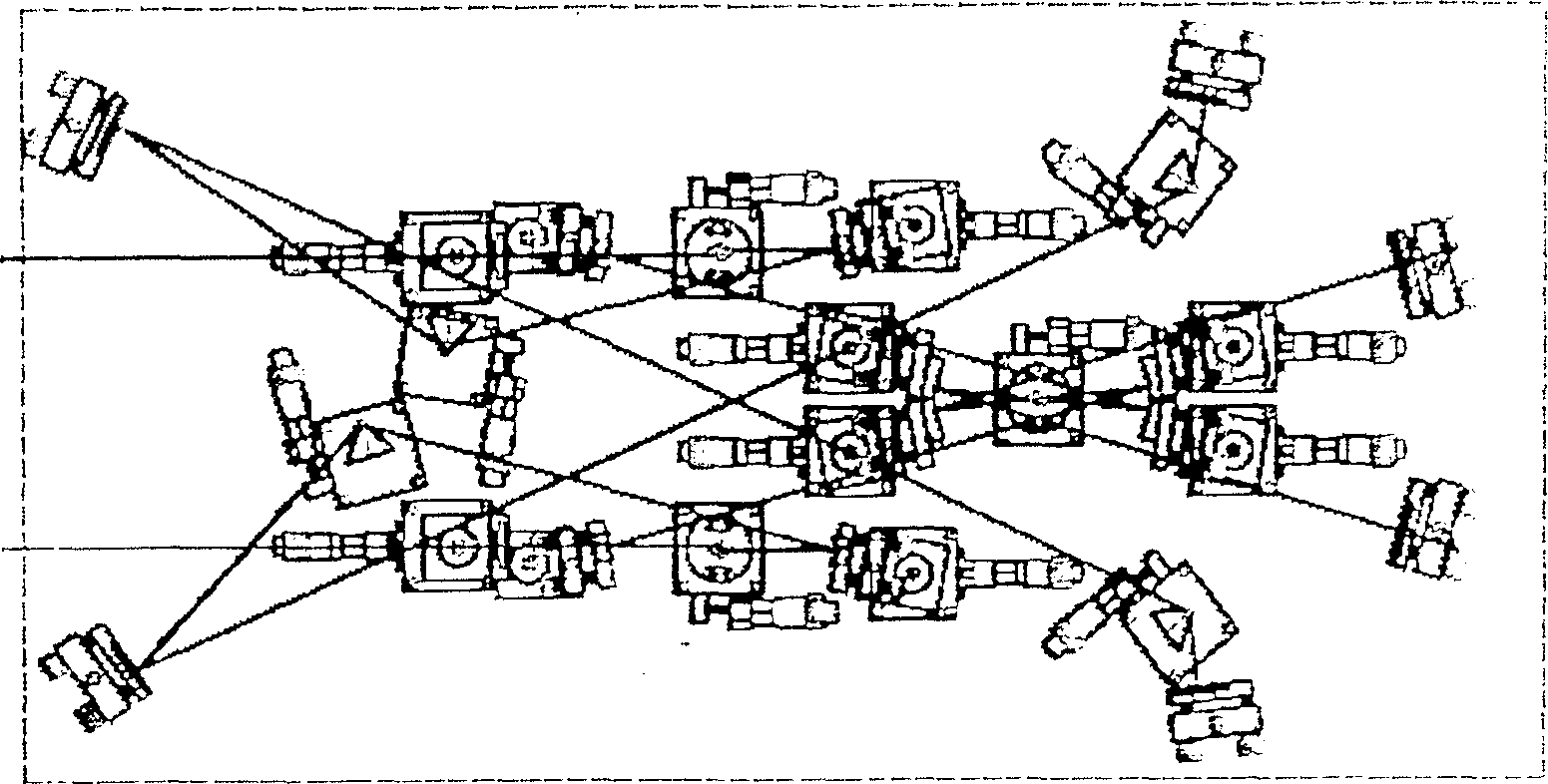
[0030] like image 3 shown, where each element is associated with figure 1 Correspondingly, all are installed on the base plate with a size of 800×400mm. The specific parameters and installation requirements for component selection are as follows:

[0031]Put the focusing lenses 1 and 2 on the adjustment frame that can adjust the lifting and left and right positions, and place the adjustment frame on the 40×40mm translation platform, and the plano-concave mirrors 5 and 7 are located on the two-dimensional adjustable fine-tuning frame , while the other plano-concave full mirror 6, 8 is located on the two-dimensionally adjustable fine-tuning frame and the translation stage of 40 × 40mm. The laser crystals 3 and 4 are located on the crystal adjustment frame and the horizontal rotating table that can adjust the pitch and angle. The two ends of the adjustment frame are connected to the water cooling cycle with rubber tubes, and the rotating crystals are respectively placed on the ...

Embodiment 2

[0037] The specific parameters and installation of each element are as in embodiment 1. However, 13 and 14 are used as planar total reflection mirrors, and a K9 glass substrate with a diameter of 25.4mm and a thickness of 4mm is coated with a broadband dielectric film that is fully reflected at 700-900nm under normal incidence; 11 and 12 are used as planar output mirrors, and A fused silica substrate with a diameter of 25.4mm and a thickness of 4mm is coated with a dielectric film with a transmittance of 10%-20% in the 750-850nm band under normal incidence.

Embodiment 3

[0039] The specific parameters and installation of each element are as in embodiment 1. However, the coupling crystal 19 is a quartz crystal with a thickness of 5 mm and a Brewster angle cut.


PUM


Abstract

The invention discloses a high-precision femtosecond laser synchronization method and device, which separates the gain medium of two femtosecond lasers to be synchronized from the synchronous coupling medium, and makes the two lasers each use its independent gain medium, and then the two The oscillating beams of the lasers are cross-coupled in a Kerr medium in the cavity, and are synchronized by means of the mutual phase modulation effect (XPM, also known as the cross-phase modulation effect). The respective gain media of the two lasers can use the same media, different types of media can also be used. Also disclosed is a synchronous device, comprising two resonant cavities and a coupling cavity, a gain crystal is respectively arranged in the two resonant cavities, a coupling crystal is arranged in the coupling cavity, and the oscillating lasers in the two resonant cavities are in the coupling cavity Overlapping in the coupled crystals produces a mutual phase modulation effect, thereby achieving synchronization. The synchronizing device of the invention has the advantages of compact structure, simple and easy mode-locking start-up, good synchronous stability and high precision.

Description

technical field [0001] The invention relates to a femtosecond laser synchronization method and device. Background technique [0002] In the research of laser technology, ultrashort pulse laser, as the time limit mark that can be controlled by human beings and its unique characteristics of revealing the transient dynamics of matter in the microcosm, has always been one of the most popular laser research contents, and its application research has penetrated into physics. The most cutting-edge topics of science, chemistry, biology, communication and other disciplines have led to the formation and development of many new disciplines, such as strong field physics, femtosecond chemistry, ultra-high-speed and large-capacity optical communication and other disciplines. Titanium-doped sapphire laser oscillator (Document 1, D.E.Spence, P.N.Kean, W.Sibbert; Opt Lett.1642(1991)) using KLM (Kerr LensModelocking) technology, with its simple structure, good stability, and output pulse widt...

Claims


Application Information

Patent Timeline
Patent Type & Authority Patents(China)
IPC IPC(8): H01S3/00
Inventor 魏志义田金荣赵玲慧张军王鹏韩海年张杰
Owner INST OF PHYSICS - CHINESE ACAD OF SCI
Why Eureka
Try Eureka