Die for injection molding of thermosetting material

An injection molding and thermosetting technology, applied in the field of molds for injection molding of thermosetting materials, can solve problems such as waste waste and achieve the effect of saving thermosetting materials

Inactive Publication Date: 2014-04-16
ZHEJIANG DAAN MOLDING TECH
View PDF6 Cites 3 Cited by
  • Summary
  • Abstract
  • Description
  • Claims
  • Application Information

AI Technical Summary

Problems solved by technology

[0003] In order to solve the waste waste problem of thermosetting materials in the prior art due to the design of flow channels, the present invention provides a mold for injection molding of thermosetting materials

Method used


Image

  • Die for injection molding of thermosetting material
  • Die for injection molding of thermosetting material
  • Die for injection molding of thermosetting material

Examples


Embodiment 1

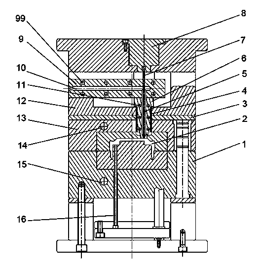
[0024] A mold for injection molding of thermosetting materials, comprising a movable mold 13, a fixed mold 1, and a runner plate 9, the runner plate is installed on the movable mold support plate 12, and a through hole is opened on the discharge runner block 6 as The discharge flow channel 5 is connected with the flow channel 10 of the flow channel plate, the heating coil 4 is installed on the outside of the discharge flow channel block, and the cooling water channel 11 is arranged in the discharge flow channel block; There is a heat insulation board 3 between the moving mold, and a cutting oil cylinder 8 is fixed on the moving mold. The output shaft of the cutting oil cylinder is fixedly connected with the cutting needle 7, and the cutting needle is installed in the inner cavity of the discharge channel 5 ; When the cutting oil cylinder pushes the cutting needle to move forward, the end of the cutting needle collides with the outlet of the discharge channel to isolate the inje...

Embodiment 2

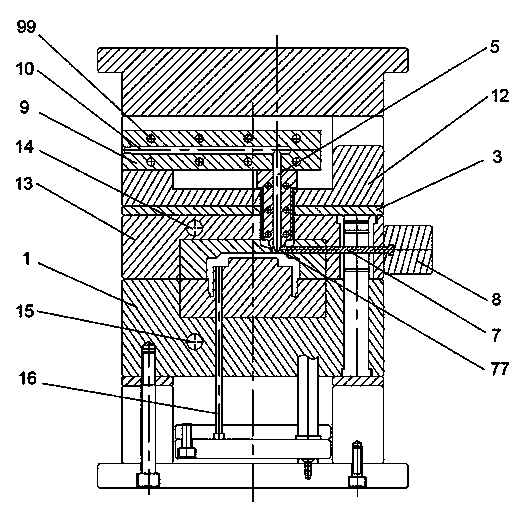
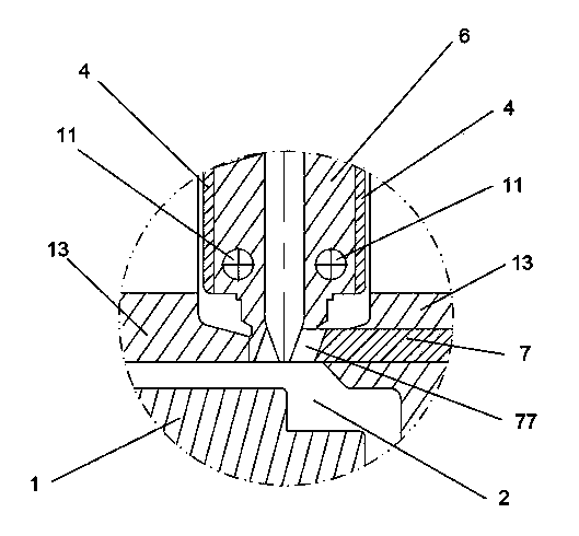
[0028] The difference between this embodiment and the first embodiment is that a cutting needle moving channel 77 perpendicular to the direction of the discharge flow channel is provided on the movable mold, and the cutting needle is installed in the cutting needle moving channel. When the cutting oil cylinder pushes the cutting needle to move forward, the end of the cutting needle collides with the discharge channel opening to isolate the injection molding cavity and the discharge channel.

[0029] In this embodiment, when the mold is ejected, the cutting oil cylinder pushes the cutting needle to move laterally to block the outlet of the outlet flow channel, and separate the outlet flow channel from the injection molding cavity, so that when the mold is ejected, the predetermined The hot material still maintains a semi-fluid state, and there is no sprue gate waste when the mold is released, which saves production materials.

Embodiment 3

[0031] The difference between this embodiment and the first embodiment is that the discharge flow channel block is made of heat insulating material, and there is no need to install heating coils outside the discharge flow channel block, and it is not necessary to add cooling water channels in the discharge flow channel.


PUM


Abstract

The invention discloses a die for the injection molding of a thermosetting material. The die comprises a moving die, a fixed die and a runner plate, wherein the runner plate is mounted on a moving die support plate, and is communicated with a discharging runner; a heat insulation layer is arranged between the moving die support plate and the moving die; a material cutting oil cylinder is fixed on the moving die; an output shaft of the material cutting oil cylinder is fixedly connected with a material cutting needle; the tail end of the material cutting needle is propped against a port of the discharging runner to isolate an injection molding die cavity from the discharging runner after the material cutting needle is driven to move forwards by the material cutting oil cylinder. According to the die, a preheated material in the discharging runner is kept in a semi-flowing state during mold stripping, and runner waste produced by a formed plastic part is avoided, so that production materials are saved.

Description

technical field [0001] The invention relates to an injection mold, especially a mold for injection molding of thermosetting materials. Background technique [0002] Thermosetting materials can be softened into a semi-fluid state when heated for the first time. After being heated to a certain temperature and solidified into shape, they cannot be reheated and softened for use, and can only be recycled as waste products. Injection molding of thermosetting materials produces sprue gate waste, which cannot be recycled, resulting in a large amount of material waste. The patent No. is 201120276395.x, and the Chinese patent titled "thermosetting mold" discloses a thermosetting injection mold. This structure only discloses the general structure of the thermosetting injection mold. mold, and the structure of the thermal insulation runner plate, the heat insulation plate is also used between the runner plate and the movable mold for temperature insulation, the preheated thermosetting ...

Claims


Application Information

Patent Timeline
Patent Type & Authority Applications(China)
IPC IPC(8): B29C45/26B29C45/40B29C45/73
CPCB29C45/26B29C45/4005B29C45/73
Inventor 施明炼
Owner ZHEJIANG DAAN MOLDING TECH
Why Eureka
Try Eureka