Feeding mechanism

A technology of feeding mechanism and conveyor belt, which is applied in the direction of destacking, transportation and packaging of objects, can solve the problems of large amount of labor and low efficiency, and achieve the effect of increasing work efficiency and reducing the amount of work labor.

Active Publication Date: 2014-04-16
GREE ELECTRIC APPLIANCES INC
View PDF5 Cites 5 Cited by
  • Summary
  • Abstract
  • Description
  • Claims
  • Application Information

AI Technical Summary

Problems solved by technology

[0003] The purpose of the present invention is to provide a feeding mechanism to solve the problems of large labor and low efficiency in remote control assembly in the prior art

Method used


Image

  • Feeding mechanism
  • Feeding mechanism
  • Feeding mechanism

Examples


Embodiment Construction

[0016] It should be noted that, in the case of no conflict, the embodiments in the present application and the features in the embodiments can be combined with each other. The present invention will be described in detail below with reference to the accompanying drawings and examples.

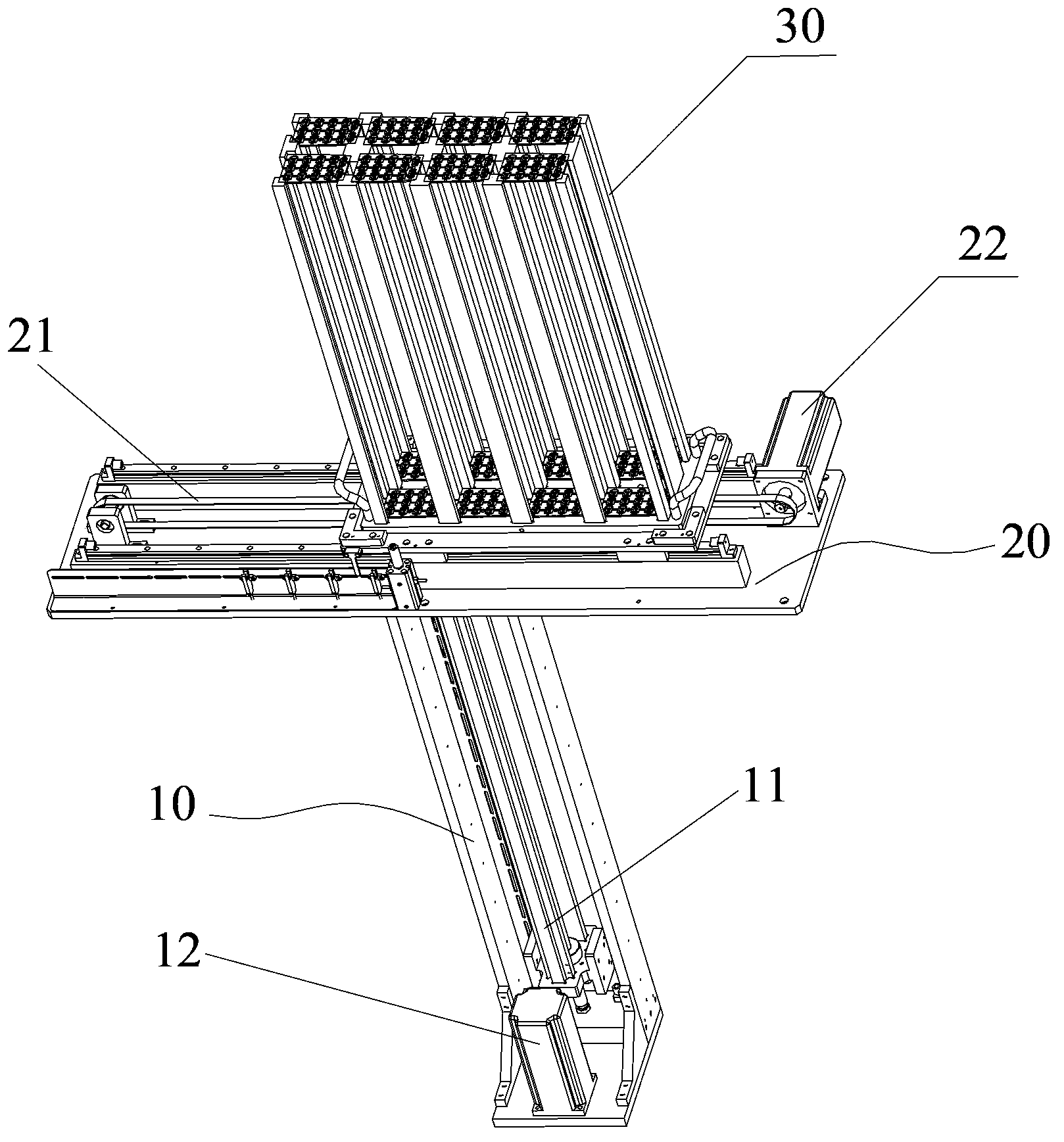
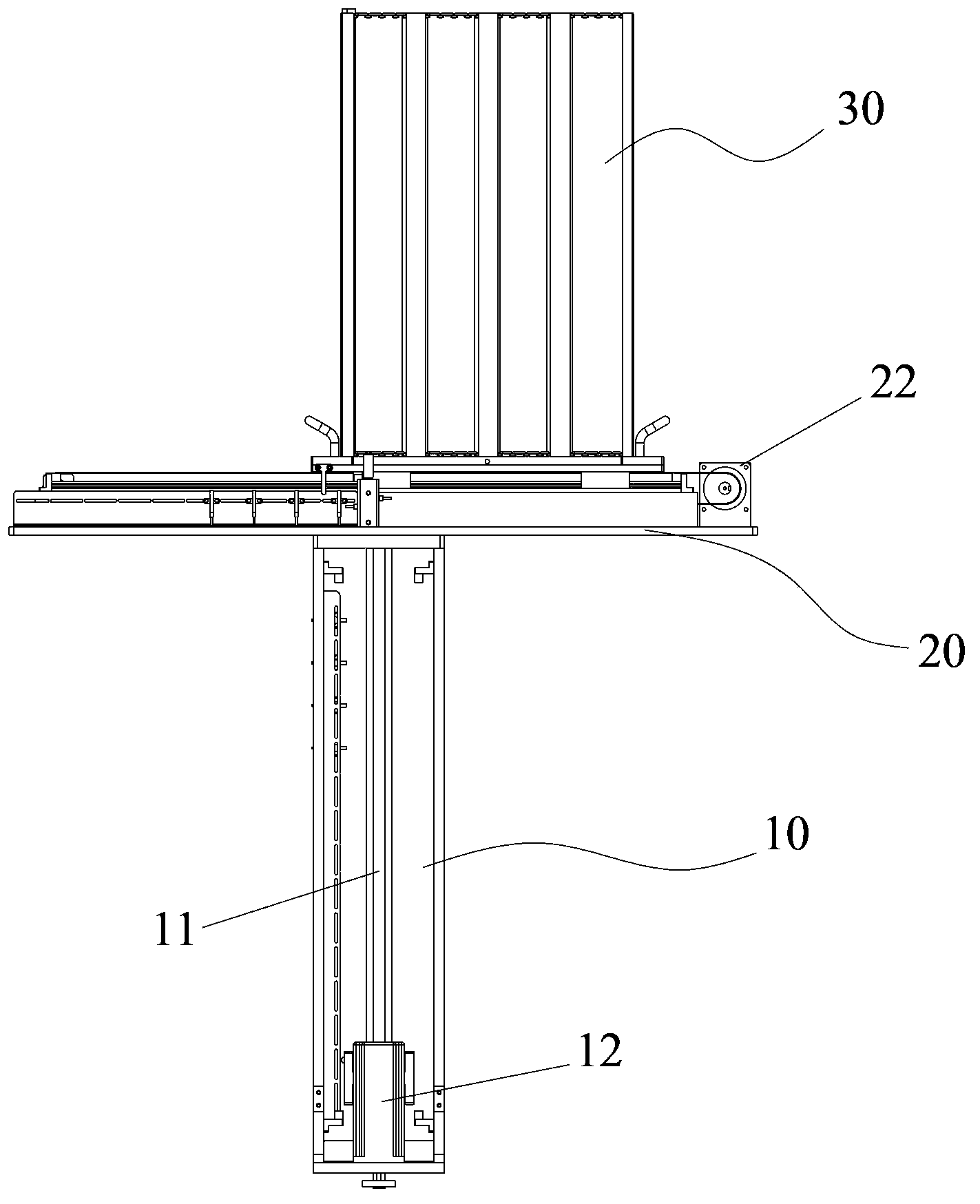
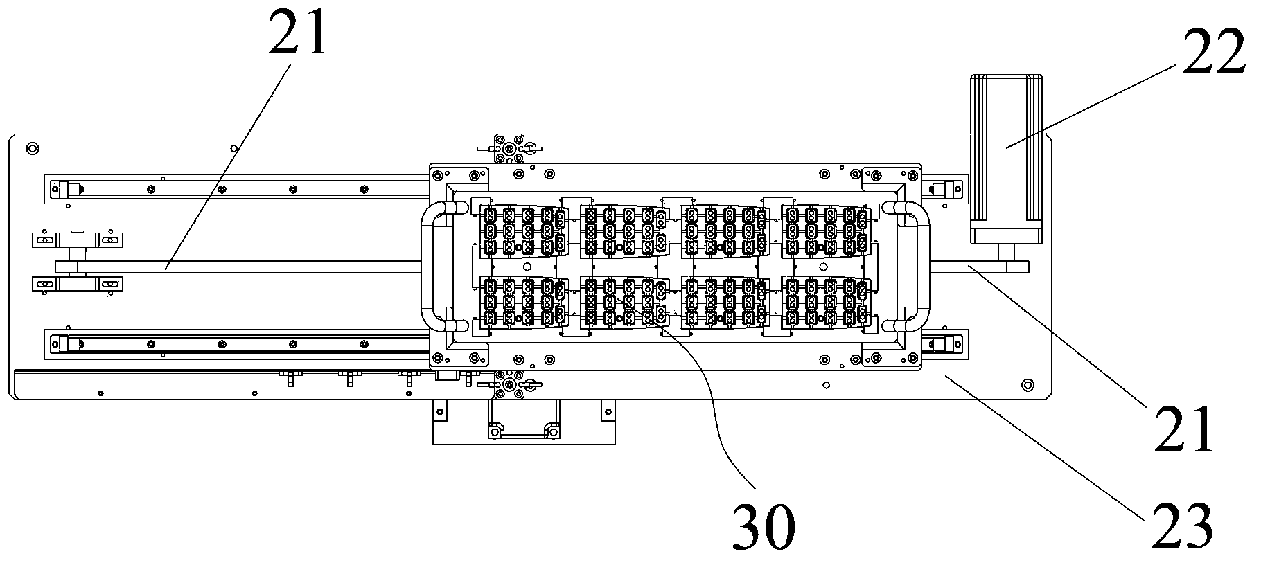
[0017] Such as Figure 1 to Figure 3 As shown, the feeding mechanism of the present embodiment includes a first mounting frame 10, a second mounting frame 20 and an object rack 30, the first mounting frame 10 is provided with a first guide rail extending longitudinally, and the second mounting frame 20 is movably installed On the first guide rail, the second mounting frame 20 is provided with a second guide rail extending in the transverse direction, and the object rack 30 is used for carrying materials, and the object rack 30 is movably installed on the second guide rail. In this embodiment, the longitudinal direction refers to the vertical direction, and the transverse direction refers to th...


PUM


Abstract

The invention provides a feeding mechanism which comprises a first installation frame (10) provided with a first guide rail extending longitudinally, a second installation frame (20) movably mounted on the first guide rail and provided with a second guide rail extending horizontally, and a material rack (30) used for carrying materials and movably mounted on the second guide rail. The feeding mechanism effectively solves the problem of the prior art that remote controller assembly requires a large amount of labor and is low in efficiency.

Description

technical field [0001] The invention relates to the technical field of material assembly, in particular to a feeding mechanism. Background technique [0002] In the prior art, the assembly of the remote control is basically manual assembly. Materials such as buttons, LCD screens, and baffles involved in the assembly of the remote control are also manually taken out and then manually assembled. Walking around causes a large amount of work labor, resulting in low assembly work efficiency. Contents of the invention [0003] The purpose of the present invention is to provide a feeding mechanism to solve the problems of large labor and low efficiency in assembling remote controllers in the prior art. [0004] In order to achieve the above object, the present invention provides a feeding mechanism, comprising: a first mounting frame, provided with a first guide rail extending longitudinally; a second mounting frame, movably installed on the first guide rail, the second mounting...

Claims


Application Information

Patent Timeline
Patent Type & Authority Applications(China)
IPC IPC(8): B65G59/02
Inventor 唐承立蔡小洪邓丽芳钟桥新闫红庆钟明生
Owner GREE ELECTRIC APPLIANCES INC
Why Eureka
Try Eureka