Self-controlled pneumatic lift car

A pneumatic lifting and pneumatic control technology, applied in the field of lift trucks, can solve the problems of automatic lifting, unsatisfactory functions, high cost of spring lifting, etc., and achieve the effect of reducing work intensity, shortening work distance and improving work efficiency

Active Publication Date: 2016-08-03
WUXI LIHU PRESSURIZE TECH CO LTD
View PDF5 Cites 0 Cited by
  • Summary
  • Abstract
  • Description
  • Claims
  • Application Information

AI Technical Summary

Problems solved by technology

[0002] In the process of product production, the operator has to transport hundreds of products in one iron frame to the processing point, process them and put them in another iron frame, that is, pick them out from the upper layer of the iron frame, and put them in another iron frame after processing. The bottom of the iron frame is picked out from the bottom of the iron frame and placed on the upper part of another iron frame. In order to pick and place the bottom products out of reach, we have to bend down and kowtow to make up for each shift. Thousands of times, the current use of hydraulic lift trucks can only be used for turnover, and will not automatically lift. Imported electro-hydraulic and spring lifts are not only expensive, but also unable to meet the requirements of the operator in terms of function.

Method used


Image

  • Self-controlled pneumatic lift car
  • Self-controlled pneumatic lift car
  • Self-controlled pneumatic lift car

Examples


Embodiment Construction

[0010] The specific implementation manners of the present invention will be further described below in conjunction with the accompanying drawings.

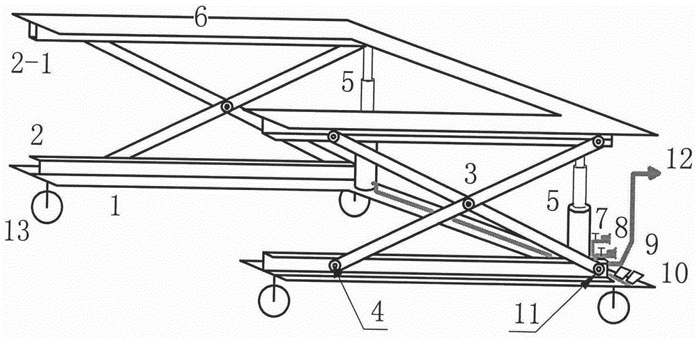
[0011] figure 1 include figure 1 Including base 1, sliding groove 2, upper chute 2-1, balance fork 3, pulley 4, cylinder 5, table top 6, lowering throttle valve 7, raising throttle valve 8, raising pedal self-locking valve 9, Down pedal self-locking valve 10, positioning shaft 11, quick joint 12, universal wheel 13 etc.

[0012] Such as figure 1 Shown, the present invention is a kind of self-control pneumatic lifting car, comprises upper and lower fixing mechanism, double fork type balance mechanism, pneumatic lifting mechanism, pneumatic control mechanism, caster mechanism.

[0013] The upper and lower fixing mechanisms include a base 1, a table top 6, a sliding groove 2, and an upper chute 2-1. The lower chute 2 is arranged on the base 1, and the upper chute 2-1 is arranged under the table top 6, and the upper and lower chute...


PUM


Abstract

The invention discloses a self-controlled pneumatic lift truck arranged at the bottom of an iron frame. The self-controlled pneumatic lift truck is characterized in that a vertical fixing mechanism, a double-fork type balance mechanism, a pneumatic mechanism, a pneumatic lift mechanism, a pneumatic control mechanism, and foot wheels are included, non-pollution transportability of compressed air is used as rising kinetic energy, a throttling valve and a pedal self-locked reversing valve are used for controlling the inlet and outlet flow of the compressed air so as to automatically control and adjust the height of a lifting table, a pedal valve with a lock can be used for supplement and correct the height of the lifting table when the lifting speed or the descending speed does not conform to operation beats, and the needed height is made to be in a proper position. The self-controlled pneumatic lift truck brings convenience to turnover, eliminates bowing and kowtow motion of operation workers, and reduces the labor intensity of workers with low investment, and fills the blank in lift trucks.

Description

technical field [0001] The invention relates to a lifting vehicle, in particular to a self-controlled pneumatic lifting vehicle. Background technique [0002] In the process of product production, the operator has to transport hundreds of products in one iron frame to the processing point, process them and put them in another iron frame, that is, pick them from the upper layer of the iron frame, and put them in another iron frame after processing. From the bottom of the iron frame until it is picked out from the bottom of the iron frame and placed on the upper part of another iron frame, in order to pick and place the bottom products out of reach, we have to bend down and kowtow to make it together. Thousands of times, the current use of hydraulic lift trucks can only be used for turnover, and will not automatically lift. Imported electro-hydraulic and spring lifts are not only expensive, but also unable to meet the requirements of the operator in terms of function. Conten...

Claims


Application Information

Patent Timeline
Patent Type & Authority Patents(China)
IPC IPC(8): B66F7/08B66F7/28
Inventor 邵宏
Owner WUXI LIHU PRESSURIZE TECH CO LTD
Why Eureka
Try Eureka