
Automatic clearance compensation type efficient sealing device

A gap compensation and sealing device technology, applied in the direction of engine sealing, engine components, mechanical equipment, etc., can solve the problems of aggravated oil mist and oil droplet overflow, hidden dangers of safe and civilized production, and no compensation amount, etc., to improve the sealing effect, The effect of reducing friction coefficient and improving wear resistance

Active Publication Date: 2014-04-16
SHENKE SLIDE BEARING
View PDF6 Cites 9 Cited by
  • Summary
  • Abstract
  • Description
  • Claims
  • Application Information

AI Technical Summary

Problems solved by technology

[0003] In this regard, traditional seals often adopt traditional sealing structures such as labyrinth seals or felts. Since the rotor (rotating shaft) will produce axial center drift during operation, the beating is also relatively large, and there are gaps during operation, or it is non-contact. labyrinth seal with gaps
At the same time, as traditional seals such as felts gradually wear out during operation, the gap will gradually increase, but there is no compensation amount, which makes the oil mist and oil droplets overflow to the outside of the oil barrier.
The oil leakage of the oil shield seriously affects the surrounding environment and the safe operation of other parts, and brings great hidden dangers to safe and civilized production. Especially in the working condition of high-speed oil intake and large amount of oil, bearing sealing is currently a technical problem that needs to be solved.

Method used


Image

  • Automatic clearance compensation type efficient sealing device
  • Automatic clearance compensation type efficient sealing device
  • Automatic clearance compensation type efficient sealing device

Examples


Embodiment Construction

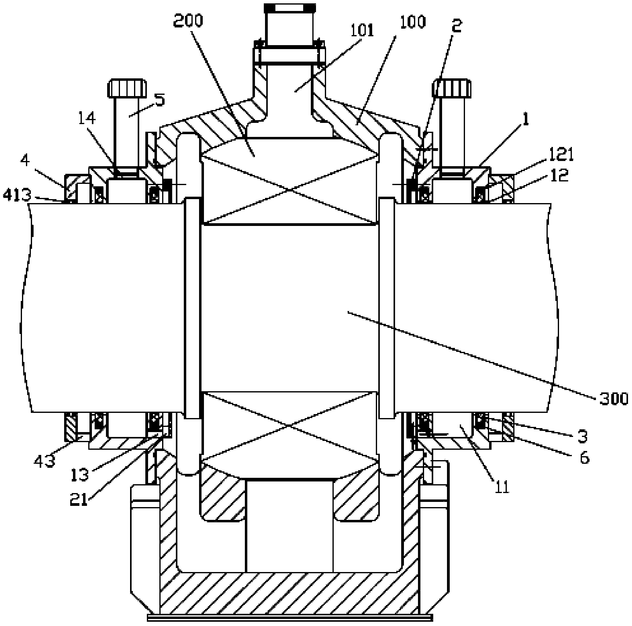
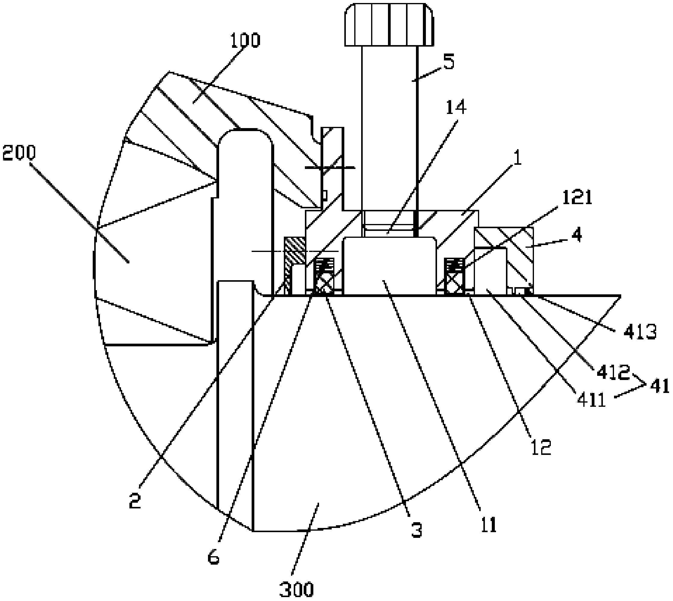
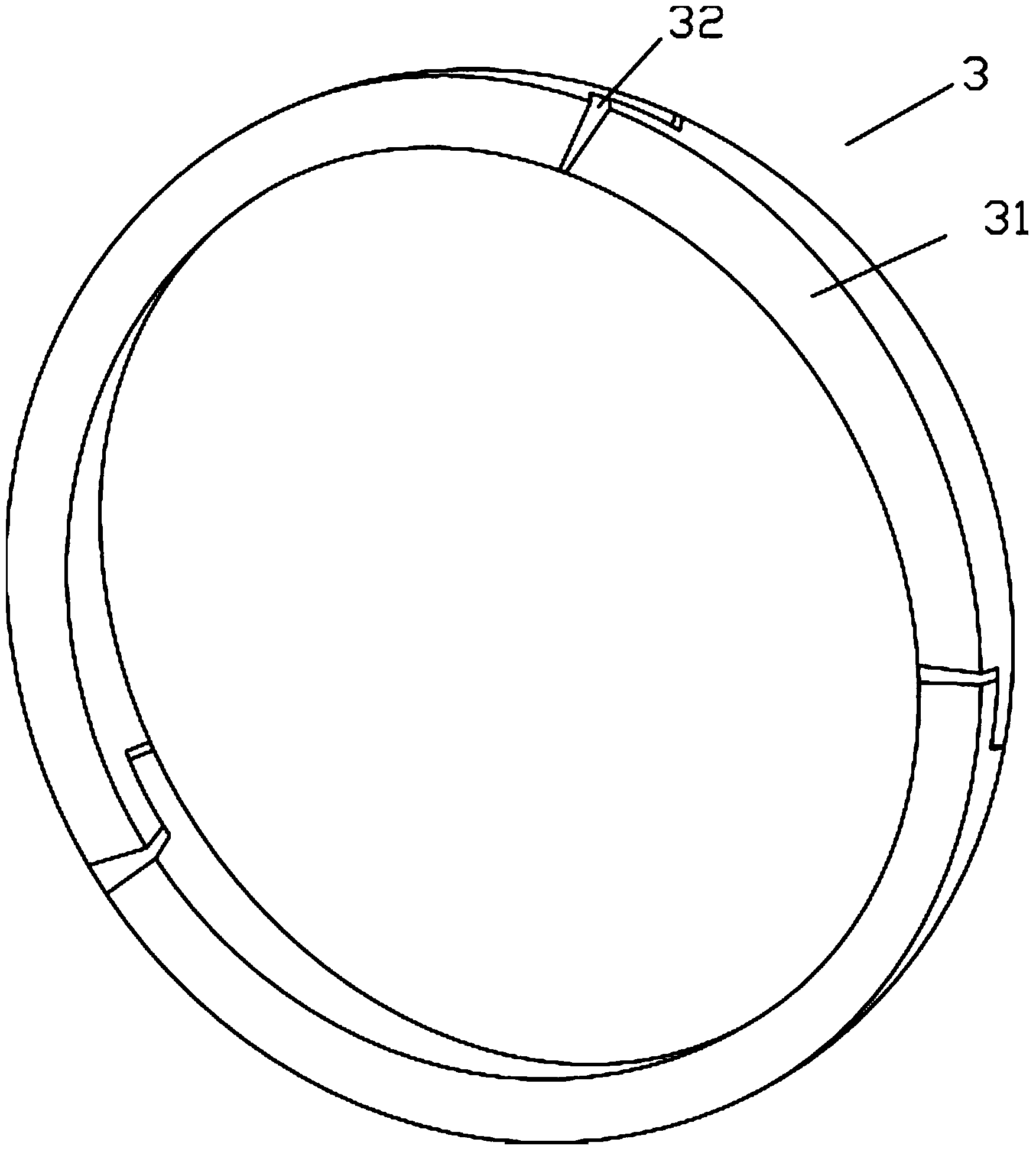
[0023] Examples, see e.g. Figures 1 to 4 As shown, a high-efficiency sealing device for automatic clearance compensation includes a bearing housing 100, bearing end covers 1 are fixed at both ends of the bearing housing 100, a bearing 200 is installed in the bearing housing 100, and the middle part of the rotating shaft 300 is fixed on the center of the bearing 200. On the inner wall, both ends of the rotating shaft 300 are inserted and sleeved on the bearing end cover 1, and the end surface of the bearing end cover 1 close to the bearing 200 is fixed with an oil retaining cover 2, and the rotating shaft 300 is inserted and sleeved in the oil retaining cover 2 A cavity 11 is formed in the middle of the bearing end cover 1, a circular through hole 12 is formed at both ends of the bearing end cover 1, an inner groove 121 is formed on the inner side wall of the circular through hole 12, and an inner groove 121 is formed in the inner groove 121. The sleeve has a sealing ring 3 an...


PUM


Abstract

The invention discloses an automatic clearance compensation type efficient sealing device. The device comprises a bearing seat, wherein bearing end covers are fixed at the two ends of the bearing seat, a bearing is mounted in the bearing seat, the middle of a rotary shaft is fixed on the inner wall of the bearing, the two ends of the rotary shaft are inserted into the bearing end covers, an oil drip pan is fixed on the end face of the side, close to the bearing, of each bearing end cover, the rotary shaft is inserted into the oil drip pans, a cavity is formed in the middle of each bearing end cover, round through holes are formed in the two ends of each bearing end cover, an inner groove is formed in the inner lateral wall of each round through hole, a sealing ring and a plurality of springs are inserted into each inner groove, one end of each spring acts on the bottom surface of the corresponding inner groove, and the other end of each spring acts on the outer lateral wall of the corresponding sealing ring. According to the automatic clearance compensation type efficient sealing device, sealing is achieved through the sealing rings composed of a plurality of arc blocks, stretching and retracting of the sealing rings are adjusted through the springs so that the sealing rings can be always attached to the rotary shaft during operation, seamless sealing is achieved, and the sealing effect is improved.

Description

Technical field: [0001] The invention relates to the technical field of bearings, in particular to an efficient sealing device for automatic clearance compensation. Background technique: [0002] For some high-speed motors, in order to ensure the safe operation of the bearings and the amount of lubricating oil, there is often a large oil inlet oil pressure and oil volume, which directly increases the pressure in the oil chamber (the central cavity of the bearing housing). In addition, part of the large amount of oil will splash out directly under the action of pressure, and part of it will enter the lubricating area and then leak out with a large amount of heat on both sides of the bearing bush. Under the action of high temperature, this part of the lubricating oil will be atomized. This further increases the pressure of the internal oil chamber and strengthens the airflow flowing outward to the bearing. This part of the airflow hits the originally splashed liquid lubricatin...

Claims


Application Information

Patent Timeline
IPC IPC(8): F16J15/16
Inventor 杨海英赵岳郑卓莹
Owner SHENKE SLIDE BEARING
Learn More