
Coil disk structures for wind power generation systems under extreme conditions

A technology for wind power generation systems and extreme conditions, applied in the shape/style/structure of winding conductors, etc., can solve the problems of low resistance to high voltage, increased heating temperature of coil discs, and low insulation of coils, so as to improve high resistance to high voltage. Voltage performance, insulation enhancement, eddy current prevention effect

Inactive Publication Date: 2016-03-09
WINDPOWER ENERGY CO LTD SHUNDE
View PDF5 Cites 0 Cited by
  • Summary
  • Abstract
  • Description
  • Claims
  • Application Information

AI Technical Summary

Problems solved by technology

If the coil disk in the above structure is made of magnetically conductive material, the relative rotation between the magnetic steel disk and the coil disk will be blocked due to the magnetic attraction between the coil disk and the magnet steel on the magnetic steel disk, and the requirements for starting wind force Higher; if the coil disk is made of conductive material, it will generate eddy current and heat. The coil disks of some wind turbines with ironless structure generally have the defects of low hardness, magnetic conductivity and electric conduction, which greatly limits the scope of application of wind turbines, and the insulation between the coils on the coil disk is low, and its resistance High voltage is low, making it impossible to apply to high voltage occasions

Method used


Image

  • Coil disk structures for wind power generation systems under extreme conditions
  • Coil disk structures for wind power generation systems under extreme conditions
  • Coil disk structures for wind power generation systems under extreme conditions

Examples


Embodiment Construction

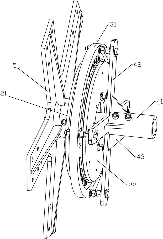
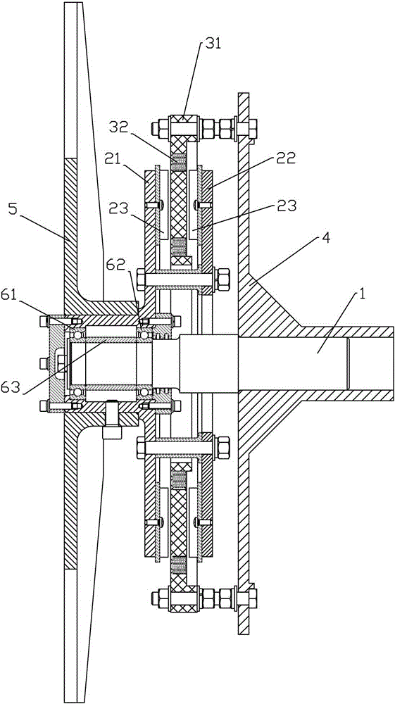
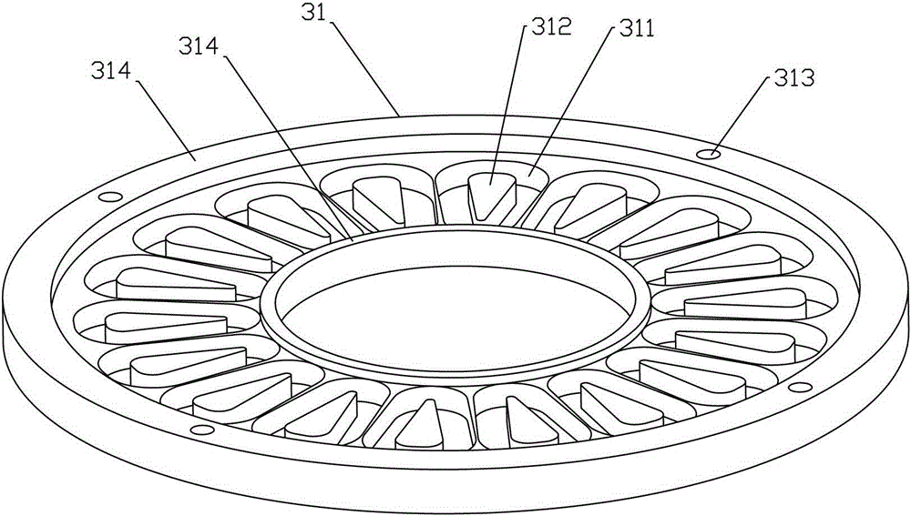
[0023] refer to Figure 1 to Figure 7 , the coil disk structure of the wind power generation system under extreme conditions of the present invention includes a coil disk 31 formed by epoxy resin and glass fiber cloth under high pressure, because epoxy resin has excellent bonding strength to the surface of metal materials and non-metal materials , good dielectric properties, good insulation, small set shrinkage, high hardness, good flexibility; and glass fiber cloth has good covering function, can ensure uniform surface structure, strong tensile properties, insulation Well, therefore, the coil disk 31 made by high-pressure molding of epoxy resin and glass fiber cloth has the characteristics of high hardness, non-conductivity, magnetic conductivity, and high temperature resistance, so as to avoid the gap between the coil disk and the magnetic steel disk due to the magnetic conduction of the coil disk. A magnetic attraction force is generated between them to hinder the rotation ...


PUM


Abstract

The invention discloses a coil panel structure used for a wind power generation system under the extreme condition. The coil panel structure comprises a coil panel formed by epoxy resin and glass fabric in a high-pressure mode, wherein the coil panel is coaxial with a main shaft of an electric generator and is located between a drive magnetic steel panel and a driven magnetic steel panel; the coil panel is provided with a plurality of coils which are evenly distributed with the center of the panel as the circle center; the coils are trapezoid; the spaces between the adjacent coils on the coil panel in the radial direction of the coil panel are the same all the time; the panel surface of one end of the coil panel is provided with installation grooves which are of a blind hole structure; the coils are placed in the installation grooves and then are packaged through potting compounds. The coil panel structure has the characteristics of being high in hardness, not conductive to electricity and magnetism, and resistant to high temperature; the starting torque of the magnetic steel panels is small; due to the facts that the trapezoid coils are evenly distributed around the center of the coil panel and the spaces between the adjacent coils in the radial direction of the coil panel are the same all the time, eddy currents are prevented; due to the fact that the installation grooves are of the blind hole structure, the coil panel is firmer; meanwhile, the coils are placed in the installation grooves and then are packaged through the potting compounds, the insulation performance between the coils is enhanced.

Description

technical field [0001] The invention relates to the technical field of wind power generators, in particular to a coil disc structure for wind power generation systems under extreme conditions. Background technique [0002] The wind power generation system is a device that uses natural wind to drive the blades, drives the generator through the blades, and converts wind energy into electrical energy. [0003] The power generation device of the traditional wind power generator is generally a drum-shaped structure, and adopts a radial magnetic flux method, mainly including a stator and a rotor. The stator is equipped with coils evenly distributed around the center of the stator and an iron core for guiding the magnetic force lines. There is a magnetic steel on it, and the rotor rotates in the stator driven by the rotation of the blades, and the movement of cutting the magnetic force line is generated, thereby generating an induced electromotive force, which can be drawn out thro...

Claims


Application Information

Patent Timeline
Patent Type & Authority Patents(China)
IPC IPC(8): H02K3/12
Inventor 李台
Owner WINDPOWER ENERGY CO LTD SHUNDE
Learn More