
Systems having multi-linkage robots and methods to correct positional and rotational alignment in multi-linkage robots

A technology for connecting devices and manipulators, which is applied in the directions of manipulators, program-controlled manipulators, and general control systems, etc.

Active Publication Date: 2014-04-16
APPLIED MATERIALS INC
View PDF4 Cites 6 Cited by
  • Summary
  • Abstract
  • Description
  • Claims
  • Application Information

AI Technical Summary

Problems solved by technology

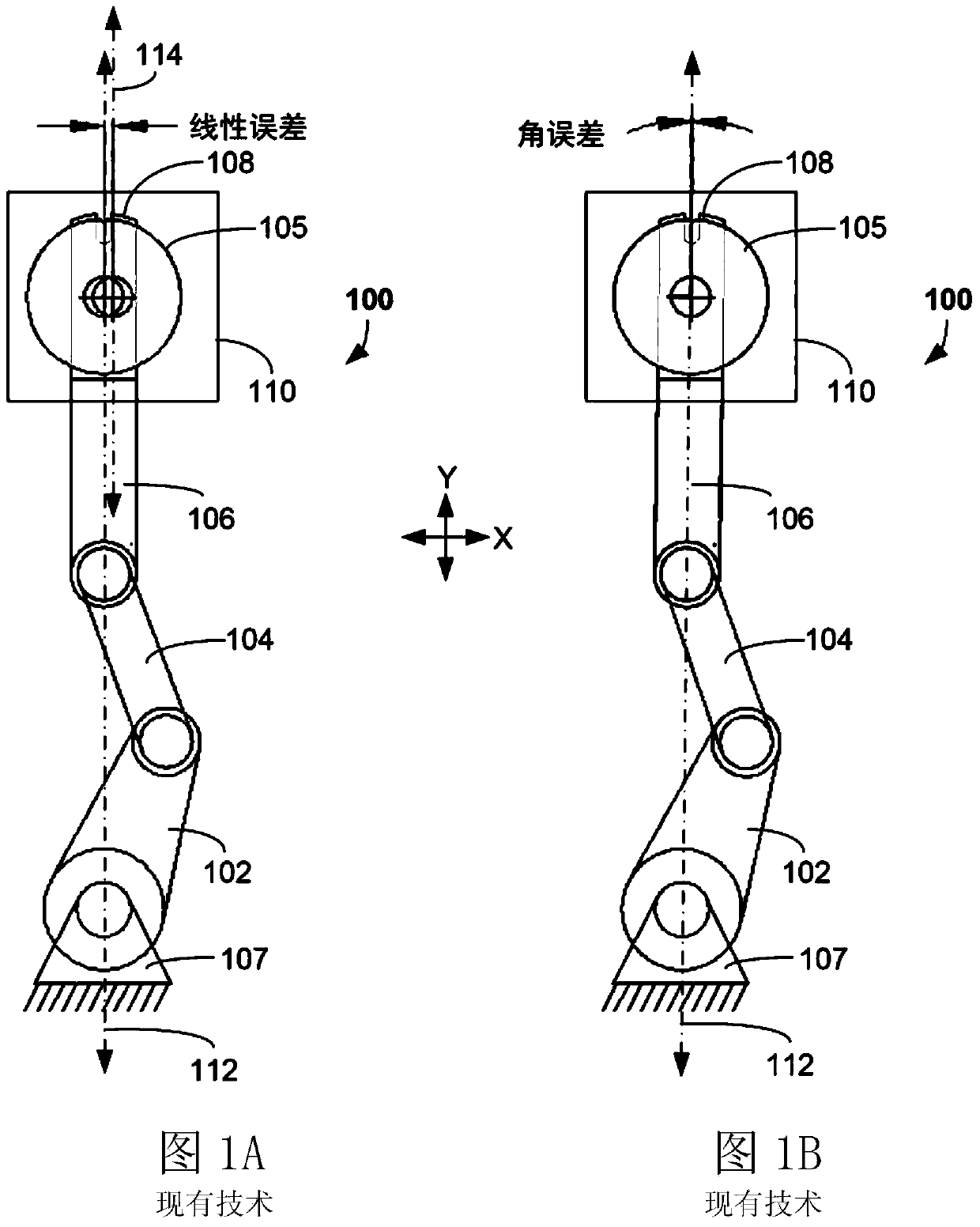
Likewise, rotational errors can be corrected, but only by introducing linear positional errors

Method used


Image

  • Systems having multi-linkage robots and methods to correct positional and rotational alignment in multi-linkage robots
  • Systems having multi-linkage robots and methods to correct positional and rotational alignment in multi-linkage robots
  • Systems having multi-linkage robots and methods to correct positional and rotational alignment in multi-linkage robots

Examples


Embodiment Construction

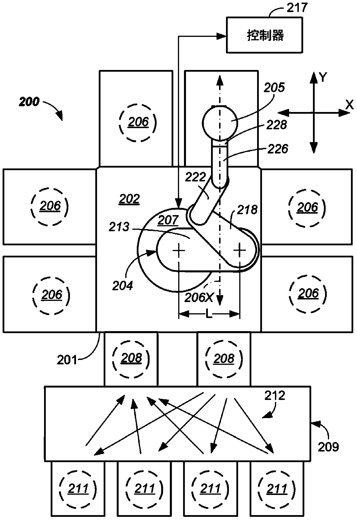
[0015] Electronic device manufacturing may require very precise and rapid transport of substrates between locations. In particular, it is desirable that such manipulators be able to be precisely oriented relative to the chambers (eg, processing chambers) they serve. However, as described herein, conventional SCARA manipulators suffer from a tradeoff between rotational and positional misalignment. As a result, the orientation of the substrate in the processing chamber may be less than optimal, thereby providing reduced clearances or instances of improper positioning (ie, misalignment). In particular, when teaching the manipulator around a handoff location (for a pick-and-place operation), positional errors, rotational errors, or both may occur. This can translate into positional or rotational errors of orientation notches used in substrate fabrication, resulting in possible process variations. Additionally, this may reduce clearances to system components such as process chamb...


PUM


Abstract

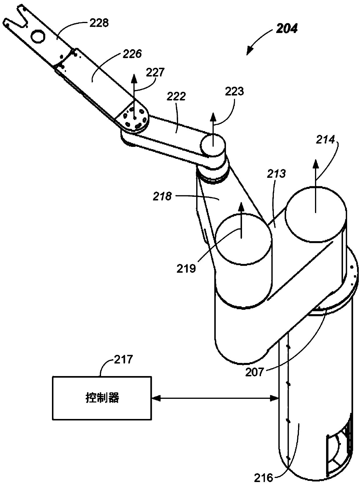
Methods of correction of rotational and linear misalignment in multi-link robots are provided. The method allows for precise orientation of an end effector to put or pick substrates at a target destination by correcting for both positional and rotational orientation errors. The method rotates a boom linkage to a position adjacent to the target destination, corrects for linear and rotational error by rotating a boom linkage as well as an upper arm link as well as extending or retracting a wrist member. Systems including long boom linkages are disclosed. Numerous other aspects are provided.

Description

[0001] related application [0002] This application claims to be entitled to the application No. 13 / 205,123 filed on August 8, 2011, named "SYSTEMS HAVING MULTI-LINKAGE ROBOTS AND METHODS TO CORRECT POSITIONAL AND ROTATIONAL ALIGNMENT IN MULTI-LINKAGE ROBOTS" (agent case No. 16361 USA), which is hereby incorporated by reference in its entirety for all purposes. technical field [0003] The invention relates to a method suitable for correcting the alignment of robotic arms in a multi-link robot. Background technique [0004] A conventional electronic device manufacturing system may include multiple processing chambers and load lock chambers. Such chambers may be included in cluster tools, for example, where multiple processing chambers may be distributed around a transfer chamber. These systems and tools may employ articulated multi-link robots that may be positioned within the transfer chamber and transport substrates between different process chambers and load locks. Fo...

Claims


Application Information

Patent Timeline
Patent Type & Authority Applications(China)
IPC IPC(8): H01L21/677B65G49/07B25J9/06B25J13/00
CPCH01L21/68H01L21/67742B25J9/1692G05B19/4015G05B2219/37608G05B2219/39041H01L21/67793
Inventor 达蒙·基思·考克斯伊贾·克雷默曼
Owner APPLIED MATERIALS INC
Learn More