
Measuring device and method for dynamic rotary error of main shaft of complete rotary equipment

A technology of rotation error and measuring device, applied in the direction of measuring device, instrument, etc., can solve problems such as difficult spindle measurement, and achieve the effects of controllable measurement error, simple error separation, and small amount of calculation.

Active Publication Date: 2017-06-23
GENERAL ENG RES INST CHINA ACAD OF ENG PHYSICS
View PDF5 Cites 0 Cited by
  • Summary
  • Abstract
  • Description
  • Claims
  • Application Information

AI Technical Summary

Problems solved by technology

Although the above inversion method, improved inversion method, and multi-step method have the advantages of simple measurement and high precision, they are still used for roundness error measurement of workpieces by means of high-precision positioning turntables, and it is difficult to directly use them in complete sets of machine tools. Measurement of Dynamic Rotational Error of Spindle of Rotary Equipment

Method used


Image

  • Measuring device and method for dynamic rotary error of main shaft of complete rotary equipment
  • Measuring device and method for dynamic rotary error of main shaft of complete rotary equipment
  • Measuring device and method for dynamic rotary error of main shaft of complete rotary equipment

Examples


Embodiment Construction

[0032] The present invention will be further described below in conjunction with accompanying drawing:

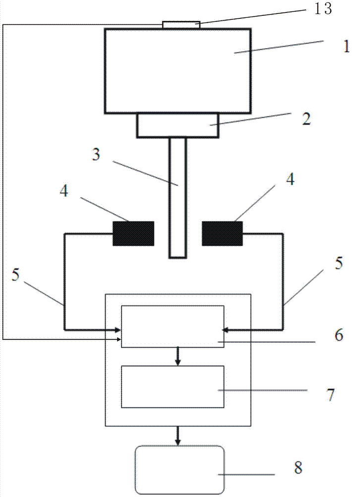
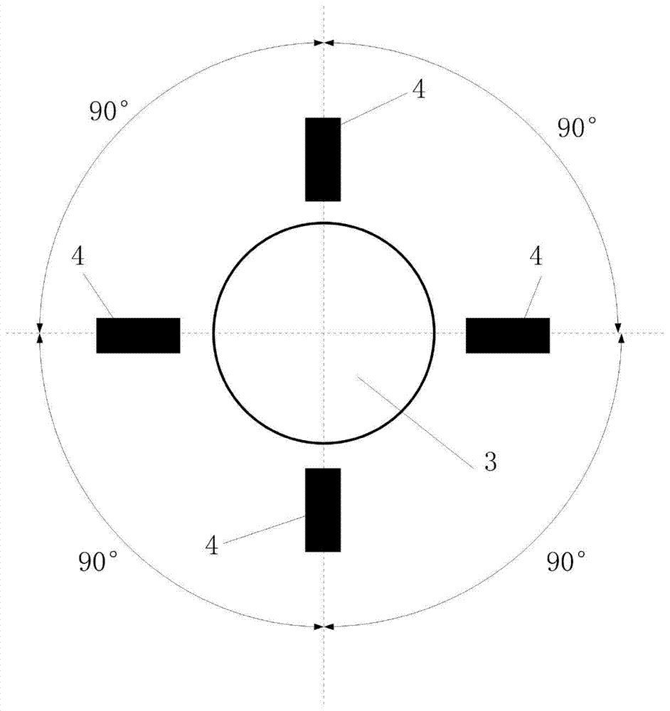
[0033] Such as figure 1 As shown, the measuring device for the dynamic rotation error of the main shaft of the complete set of rotary equipment in the present invention includes a grating encoder 13, a connecting positioning column 2, a standard rod 3, a displacement sensor 4, a data collector 6, a signal conditioner 7 and a host computer 8, The grating encoder 13 is used to detect the rotational speed of the main shaft 1 and output the Z pulse signal, connect the positioning column 2 installed between the standard rod 3 and the main shaft 1, and connect the first end of the positioning column 2 (ie figure 1 The upper end of the middle) is connected with the main shaft 1, and connected with the second end of the positioning column 2 (ie figure 1 The lower end of the middle) and the first end of the standard rod 3 (ie figure 1 The upper end of the middle) is connected, the...


PUM


Abstract

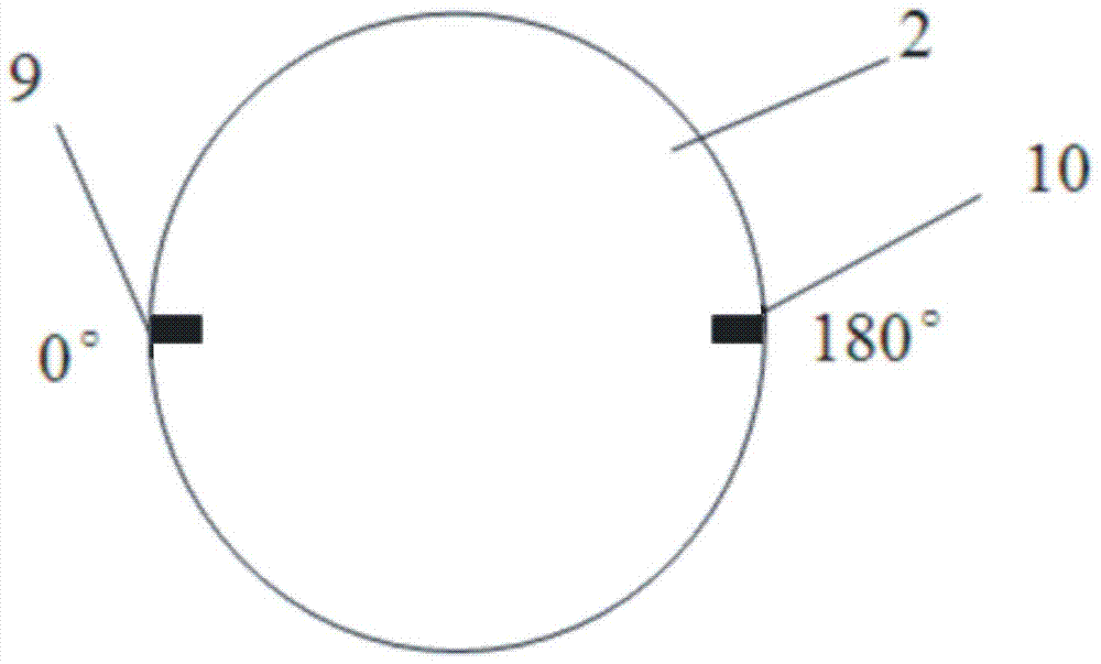
The invention discloses a device for measuring the dynamic revolution error of a main shaft of a set of revolution equipment. A connecting reference column is mounted between a reference rod and the main shaft, the measuring ends of four displacement sensors are arranged in the circumference of the standard rod and used to detect displacement of the reference rod, the signal output end of each displacement sensor is connected with a data collector, a signal conditioner and a host computer, and the end surface of the connecting reference column and the end surface, connected to the end surface of the connecting reference column, of the reference rod are provided with two symmetrical marks respectively. The invention also discloses a method for measuring the dynamic revolution error of the main shaft of the set of revolution equipment. The method comprises that the main shaft is rotated, and the displacement sensors record numbers; the main shaft is rotated again after the reference rod rotates for 180 degrees, and the displacement sensors record numbers; Fourier transform is carried out on data; and the radial revolution error of the main shaft is calculated according to the data. The error separating technology in the courter-rotating method is improved to measure the dynamic revolution error of the main shaft of the set of equipment, the measuring precision is substantially improved, and the device and method can be widely popularized and applied.

Description

technical field [0001] The invention relates to a measurement device and a measurement method for the dynamic rotation error of a spindle of a complete set of rotary equipment such as a precision machine tool or a precision centrifuge, and belongs to the technical field of precision instrument manufacturing and measurement. Background technique [0002] As the core part of a complete set of equipment such as precision machine tools, precision turntables, and precision centrifuges, the measurement of the rotation error of the spindle greatly affects the machining accuracy of precision parts and the calibration accuracy of inertial instruments. Especially in the field of precision machining, many factors such as machine tool thermal deformation, structural error, spindle rotation error, and environmental vibration are factors that affect the machining error of mechanical parts. As the machining accuracy of machine tools reaches the sub-micron or even nanometer level, the machi...

Claims


Application Information

Patent Timeline
Patent Type & Authority Patents(China)
IPC IPC(8): G01B21/00
CPCG01B21/00G01B21/02
Inventor 凌明祥周继昆李思宗阳红刘信恩莫军张荣尹益辉
Owner GENERAL ENG RES INST CHINA ACAD OF ENG PHYSICS
Learn More