
Single track high-efficiency automatic blow molding machine

A single-track, blow molding machine technology, applied in the field of single-track high-efficiency automatic blow molding machines, can solve the problems of complex blow mold template design, complex mechanism, and affecting blow molding machine blowing efficiency

Inactive Publication Date: 2016-02-03
徐光中
View PDF4 Cites 0 Cited by
  • Summary
  • Abstract
  • Description
  • Claims
  • Application Information

AI Technical Summary

Problems solved by technology

In the above structure, in order to keep the divided preforms into the blowing mold at the distance after the preforms are divided, it is necessary to directly send the grasped preforms into the blowing mold through the fork action of the preform moving device to realize the preform movement. The whole action process requires the reciprocating operation of the fork. Not only is the action cumbersome and the mechanism is complicated, it seriously affects the blowing efficiency of the blow molding machine. At the same time, the action of the fork will interfere with the template of the blowing mold, resulting in the complexity of the template design of the blowing mold. change

Method used


Image

  • Single track high-efficiency automatic blow molding machine
  • Single track high-efficiency automatic blow molding machine
  • Single track high-efficiency automatic blow molding machine

Examples


Embodiment Construction

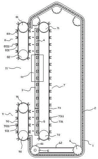
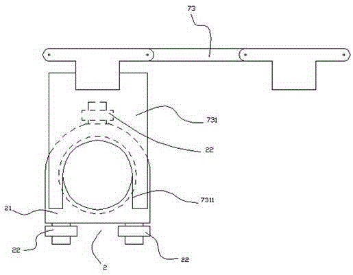
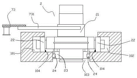
[0022] Such as Figure 1-3 As shown, a single-track high-efficiency automatic blow molding machine includes a working track 1 for the cyclic movement of the preform seat 2. The working track 1 is provided with a gap 11 at a certain straight line position. The inside of the gap 11 or The blowing track 3 with a length shorter than the notch 11 and a linear layout is arranged side by side at a distance from the outside. inside.

[0023] The two ends of the blowing track 3 are respectively provided with a feeding moving track 4 and a reset moving track 5, and the feeding moving track 4 and the reset moving track 5 can be moved outwards to be connected with the two ends of the gap 11 of the working track 1 respectively. connect.

[0024] The two corners of the working track 1 are respectively provided with a preform seat driving turntable 6 with a bayonet 61. During work, the preform seat 2 is placed on the working track by the rotation of the above two driving turntables 6. 1 i...


PUM


Abstract

The invention discloses a single-track high-efficient automatic bottle blowing machine. The single-track high-efficient automatic bottle blowing machine comprises a working track, wherein a gap is arranged at a part of a certain straight line section of the working track, blowing tracks are arranged on the inner side or the outer side of the gap at a certain distance in parallel, a feed moving track and a reset moving track are respectively arranged at the two ends of the blowing track, and the feed moving track and the reset moving track can move outwards and are respectively linked with the two ends of the gap of the working track; the working track is respectively provided with bottle parison base driving turntables at two corners at a starting section; and blowing bottle parison base driving mechanisms are mounted on the inner sides of the feed moving track, the blowing track and the reset moving track; a parison separation mechanism is arranged on the outer side of the feed moving track; and a parison closing mechanism is arranged on the outer side of the reset moving track. The design of the invention has the advantages of realizing fast parison movement after separation of bottle parisons, preventing interfering with a mold plate structure of a blowing mold, simplifying the structure of the blowing mold, effectively upgrading the blowing efficiency of the bottom parisons and realizing very high economic value.

Description

technical field [0001] The invention relates to a single-track bottle blowing machine, in particular to a single-track high-efficiency automatic bottle blowing machine. Background technique [0002] In the current single-track automatic bottle blowing machine, in order to realize the reciprocating use of the preform seat, its working track is a closed track, and the preform seat is always cyclically running in the closed track. In practice, in order to improve the preform Preheating efficiency, the operation of the preforms on the heating track section is carried out by mutual extrusion between the preform seats, so as to obtain the densest distribution of preforms and improve the preheating efficiency of preforms. [0003] However, there is a big problem in the above structural design, that is, when the preforms run to the end of the heating track section, the preforms need to be separated by the preform separating mechanism, so that the preforms entering the blowing mold c...

Claims


Application Information

Patent Timeline
Patent Type & Authority Patents(China)
IPC IPC(8): B29C49/28B29C49/42B29C31/00
Inventor 徐光中
Owner 徐光中
Learn More