
An ink jet control circuit

A control circuit and inkjet technology, applied in printing and other directions, can solve problems such as affecting printing quality and insufficient preheating temperature of inkjet heads.

Inactive Publication Date: 2014-02-19
MICROJET TECH
View PDF8 Cites 5 Cited by
  • Summary
  • Abstract
  • Description
  • Claims
  • Application Information

AI Technical Summary

Problems solved by technology

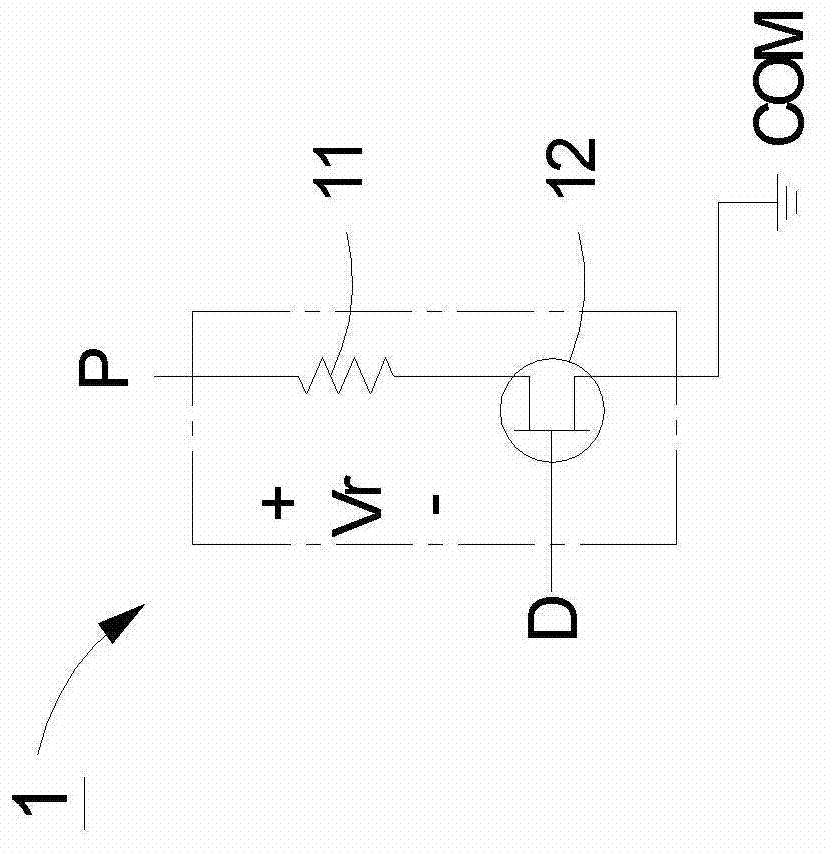
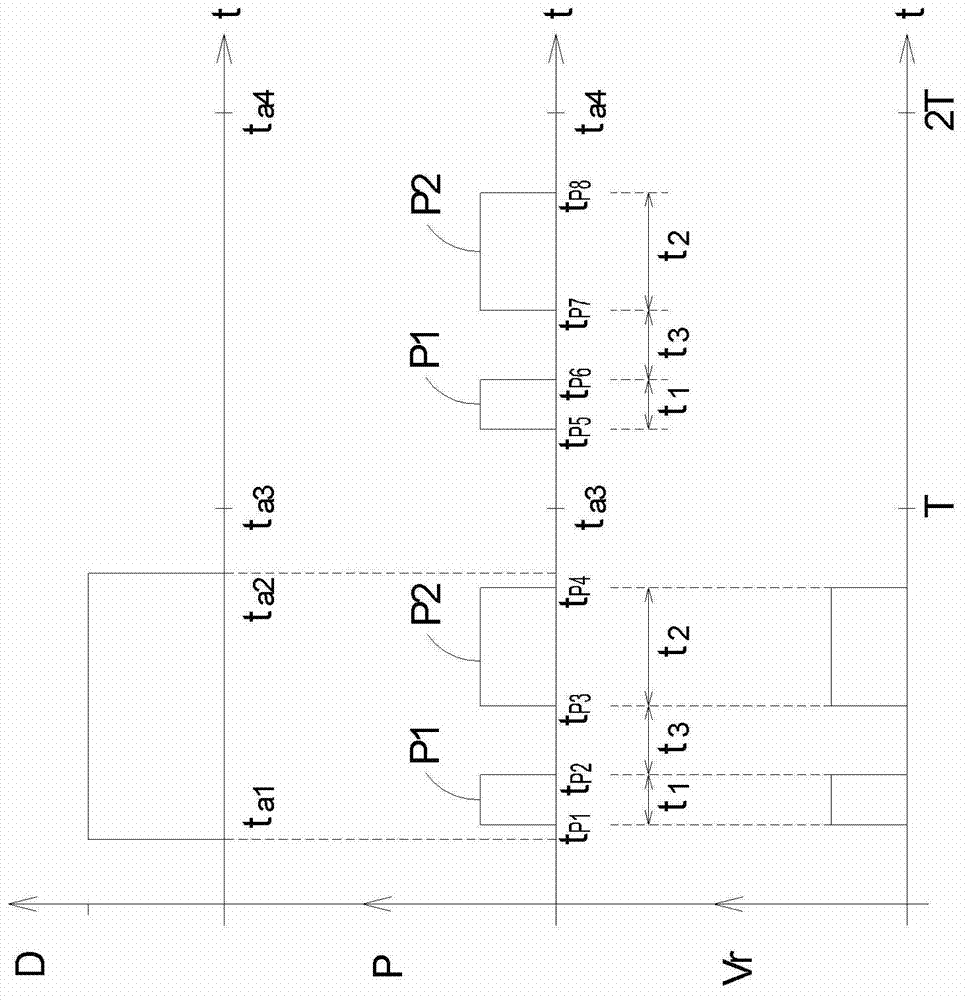
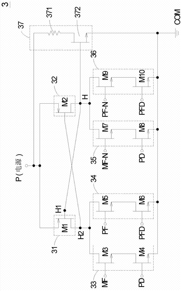
[0010] The main purpose of the present invention is to provide an inkjet control circuit, which is to make the heater heat part of the ink and generate bubbles when the printing data signal and the heating control signal are high potential signals, and then push the ink out of the ink. Heating the inkjet hole of the chip; on the contrary, when the printing data signal is a low potential signal and the preheating control signal and the preheating data signal are high potential signals, the heater is controlled to preheat part of the ink and the inkjet head to make it The preheating temperature of the inkjet head is easy to control and the preheating efficiency is improved, so as to solve the problem in the known technology that only the inkjet drive circuit that will print the column data will preheat part of the ink and the inkjet head, causing the inkjet head to preheat Insufficient temperature, which will affect the printing quality and other shortcomings

Method used


Image

  • An ink jet control circuit
  • An ink jet control circuit
  • An ink jet control circuit

Examples


Embodiment Construction

[0040] Some typical embodiments embodying the features and advantages of the present invention will be described in detail in the description in the following paragraphs. It should be understood that the invention is capable of various changes in different aspects without departing from the scope of the invention, and that the description and illustrations therein are illustrative in nature and not limiting. this invention.

[0041] Generally speaking, the heating chip arranged inside the structure of the inkjet head has a plurality of inkjet holes arranged on the heating chip, and each inkjet hole has an inkjet control circuit to control the inkjet Whether the hole ejects ink, because the inkjet head has multiple ink ejection holes that need to be controlled, so there must be multiple ink ejection control circuits on the heating chip. The following will take a single ink ejection control circuit as an example to illustrate, but not This is the limit.

[0042] see image 3 ...


PUM


Abstract

The invention relates to an ink jet control circuit. A heating chip disposed inside an ink-jetting head structure comprises a heater and six switch circuits and receives a power signal, a printing data signal, a preheating data signal, a heating control signal, and a preheating control signal. When the printing data signal and the heating control signal are maintained at high potential, the heater heats a part of ink and generates bubbles such that the ink is pushed out of the ink-jetting holes on the heating chip. When the preheating control signal and the preheating data signal are maintained at high potential, the heater preheats a part of the ink and the ink-jetting head. Therefore, the ink-jetting head has easily-controlled preheating temperature and high preheating efficiency.

Description

technical field [0001] The invention relates to an inkjet control circuit, in particular to an inkjet control circuit suitable for a heating chip of an inkjet head. Background technique [0002] In recent years, with the popularization of personal computers and the rapid development of the Internet, inkjet printers have become very common peripheral devices, widely used in homes, personal studios, and even in various industries. The main advantages of inkjet printers are low price, low noise during operation, and excellent printing quality, and they can be printed on various media, such as general paper, special inkjet printing paper, photo paper, and special transparencies. [0003] There are many factors that affect the printing quality of inkjet printers, such as ink composition, paper selection, ink supply method of ink cartridges, etc. However, ink cartridges are an indispensable component for any inkjet printer, and the quality of ink cartridges Bad is more related to...

Claims


Application Information

Patent Timeline
IPC IPC(8): B41J2/05
Inventor 余荣侯廖文雄张正明戴贤忠
Owner MICROJET TECH
Learn More