Liquid spray chip of printing module of rapid prototyping device and liquid spray control circuit thereof

A technology of a printing module and a forming device, which is applied to the printing device, printing and other directions, can solve the problems of increasing the volume of the printing module 1, increasing the cost of the carrier and the printing ink cartridge, etc.

Active Publication Date: 2016-08-10
MICROJET TECH
View PDF6 Cites 0 Cited by
  • Summary
  • Abstract
  • Description
  • Claims
  • Application Information

AI Technical Summary

Problems solved by technology

[0006] However, when the rapid prototyping jet printing operation of this 3D object is implemented, in addition to containing black and color inks, the printing ink cartridge 12 needs to contain an additional high-viscosity adhesive to bond the construction materials, and then can be layered. Layers are stacked to form 3D objects. Therefore, traditional rapid prototyping devices need to be equipped with additional carriers and printing ink cartridges to accommodate high-viscosity adhesives. In this way, the overall volume of the printing module 1 will increase. , while increasing the cost of the carrier and print cartridges

Method used


Image

  • Liquid spray chip of printing module of rapid prototyping device and liquid spray control circuit thereof
  • Liquid spray chip of printing module of rapid prototyping device and liquid spray control circuit thereof
  • Liquid spray chip of printing module of rapid prototyping device and liquid spray control circuit thereof

Examples


Embodiment Construction

[0087] Some typical embodiments embodying the features and advantages of the present invention will be described in detail in the description in the following paragraphs. It should be understood that the present invention can have various changes in different aspects without departing from the scope of the present invention, and the descriptions and illustrations therein are used as illustrations in nature rather than limiting the present invention .

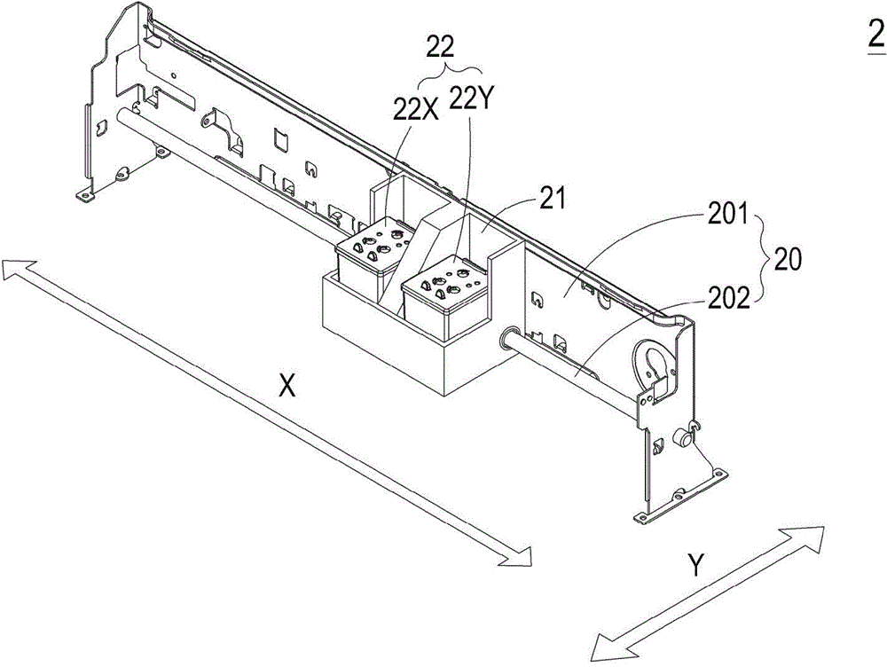
[0088] see figure 2 , which is a structural schematic diagram of the printing module of the rapid prototyping device according to the first preferred embodiment of the present invention. Such as figure 2 As shown, the printing module 2 is suitable for a rapid prototyping device (not shown), and includes a printing platform 20, a bearing seat 21 and a plurality of modular liquid spray boxes 22, and the printing platform 20 includes a frame body 201 and a transmission shaft 202, and the transmission shaft 202 straddles the fr...


PUM


Abstract

The invention relates to a liquid spray chip which has a length and a width constituting a total area region. The total area region contains a non-wiring area and a wiring area. At least three liquid supply tanks are arranged in the non-wiring area in parallel, and each liquid supply tank is communicated with one liquid storage chamber in the cartridge body of a liquid spray cartridge. A liquid spray control circuit is arranged in the wiring area. The liquid spray control circuit includes multiple liquid droplet generators, and each liquid droplet generator is composed of a heating resistor, a driving transistor, and a liquid spray hole. The liquid spray control circuit receives power signals, print data signals, preheating data signals, preheating control signals, reverse preheating control signals, heating control signals, and reverse heating control signals, and is connected with a common endpoint to control the liquid droplet generators.

Description

technical field [0001] The invention relates to a liquid spraying chip and a liquid spraying control circuit thereof, in particular to a liquid spraying chip and a liquid spraying control circuit of a printing module of a rapid prototyping device. Background technique [0002] Rapid prototyping technology (RP technology for short) is developed based on the concept of building a pyramid-like layer stacking molding. Automatically and quickly convert the design scheme of any complex shape into a 3D solid model, which greatly shortens the development cycle of new products and reduces the cost of research and development, and can ensure the time to market of new products and the first-time success rate of new product development. Molding technology provides a more complete and convenient product design communication tool for technical personnel, as well as between technical personnel and enterprise decision makers, product users and other non-technical personnel, thus significant...

Claims


Application Information

Patent Timeline
IPC IPC(8): B41J2/21B41J29/38
CPCB41J2/0458B41J2/04541B41J2/04528B41J2/15B41J2/2114B41J2/1753B41J2/17553B41J2/17513
Inventor 廖文雄黄启峰
Owner MICROJET TECH
Why Eureka
Try Eureka