Guide hydraulic control system with oil changing function

A technology of hydraulic control system and pilot control valve, which is applied in fluid pressure actuators, servo motor components, mechanical equipment, etc., can solve the problem of difficult preheating of hydraulic oil, achieve the goal of improving preheating efficiency and shortening preheating time Effect

Inactive Publication Date: 2012-11-14
LIUZHOU LIUGONG EXCAVATORS +2
View PDF3 Cites 4 Cited by
  • Summary
  • Abstract
  • Description
  • Claims
  • Application Information

AI Technical Summary

Problems solved by technology

[0003] The technical problem to be solved by the present invention is to provide a pilot hydraulic control system that shortens the preheating time of the pilot hydraulic oil in view of the problem that the hydraulic oil between the pilot control valve and the reversing valve is difficult to preheat in the existing pilot hydraulic control system

Method used


Image

  • Guide hydraulic control system with oil changing function
  • Guide hydraulic control system with oil changing function
  • Guide hydraulic control system with oil changing function

Examples


Embodiment 1

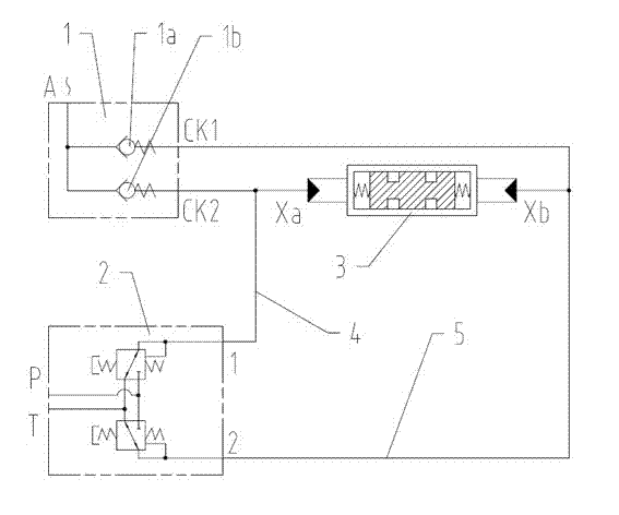
[0018] figure 1 A schematic diagram of the pilot hydraulic control system of the present invention is shown. Such as figure 1 As shown, port 1 of the pilot control valve 2 is connected to the Xa oil chamber of the reversing valve 3 through the left pipeline 4, and port 2 of the pilot control valve 2 is connected to the Xb oil chamber of the reversing valve 3 through the right pipeline 5. The oil circuit includes a one-way valve group 1 and an oil change inlet A. The one-way valve group 1 includes two one-way valves 1a and 1b. The oil outlet CK2 of one check valve 1a in the check valve group communicates with the left pipeline 4, and the oil outlet CK1 of the other check valve 1b communicates with the right pipeline 5. In the pilot hydraulic control system of the present invention, when the engine is warmed up, the pilot control valve is in the neutral position, and the oil change inlet port of the oil change oil circuit introduces the preheated hydraulic oil into the left pi...

Embodiment 2

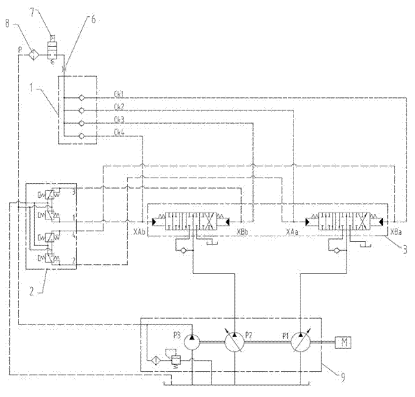
[0020] figure 2 Shows the application of the pilot hydraulic control system of the present invention on hydraulic excavators, such as figure 2 As shown, in the hydraulic excavator, for the sake of stability and safety, two sets of pilot hydraulic control systems in parallel are used. In the oil change circuit, the one-way valve group includes four one-way valves, which are respectively connected to two sets of pilot control systems. In the left and right pipelines, the oil inlets of the check valves in the one-way valve group are connected to each other, and then the restrictor 6, the solenoid valve 7 and the rear filter 8 are connected in series, and the oil change inlet P passes through the pipeline and the pump group The oil outlet pipeline of the pilot pump P3 in No. 9 is connected to obtain the preheated oil source.

Embodiment 3

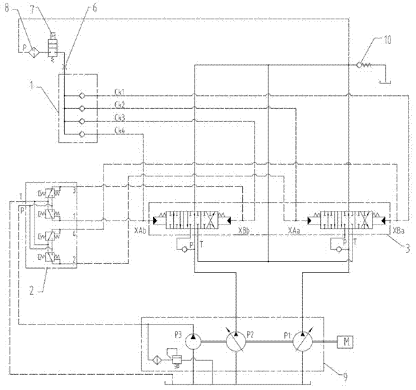
[0022] image 3 Another application of the pilot hydraulic control system of the present invention on hydraulic excavators is shown, such as image 3 As shown, the difference from Embodiment 2 is that the oil change inlet P communicates with the main oil return before the oil return back pressure valve 10 to obtain a preheated oil source.


PUM


Abstract

The invention relates to a guide hydraulic control system with oil changing function, which is aimed at solving the problem of long preheating time in the existing guide hydraulic control oil line. The guide hydraulic control system comprises a guide control valve, a change valve and an oil-changing oil line; an opening 1 of the guide control valve is connected with an Xa oil chamber of the change valve through a left pipeline; an opening 2 of the guide control valve is connected with an Xb oil chamber through a right pipeline; the oil-changing oil line comprises a one-way valve unit and an oil-changing inlet; the one-way valve unit comprises two one-way valves; oil inlets of the one-way valves are communicated with each other and then is communicated with the oil-changing inlet; an oil outlet of one one-way valve in the one-way valve unit is communicated with the left pipeline; and an oil outlet of the other one-way valve is communicated with a right pipeline. According to the guide hydraulic control system, preheated hydraulic oil for hydraulic oil in the guide control pipeline can be replaced through the oil-changing oil line during preheating a machine, so that preheating efficiency can be improved, and preheating time can be shortened.

Description

technical field [0001] The invention relates to a hydraulic control system, in particular to a pilot hydraulic control system with oil changing function. Background technique [0002] For hydraulically driven equipment, the reversing valve is usually driven and controlled by the pilot control valve, and the action control of the hydraulic working equipment is realized through the action of the reversing valve. When the hydraulic drive equipment works in a cold climate environment, due to the high viscosity of the hydraulic oil at the beginning of the operation, the relevant actions of the hydraulic drive equipment will lag behind, which may endanger the personal safety of the construction personnel. In general, in order to reduce the action hysteresis, operators of hydraulically driven equipment often need to pressurize the hydraulic cylinder for a long time to increase the temperature of the hydraulic oil in the control circuit after starting the engine of the machine, ther...

Claims


Application Information

Patent Timeline
Patent Type & Authority Applications(China)
IPC IPC(8): F15B13/02
Inventor 李欲江刘剑李文新王中龙覃世伍
Owner LIUZHOU LIUGONG EXCAVATORS
Why Eureka
Try Eureka