Steel scrap baking system

A scrap steel and steel plate technology, which is applied in the field of scrap steel baking system, can solve the problems of short replacement and maintenance cycle, increased expenses, complicated pipeline design, etc., to simplify the design of pipeline routing, increase costs and simplify operation steps Effect

Pending Publication Date: 2019-06-21
LUOYANG WODA MACHINERY TECH DEV
View PDF0 Cites 5 Cited by
  • Summary
  • Abstract
  • Description
  • Claims
  • Application Information

AI Technical Summary

Problems solved by technology

[0003] The existing scrap steel preheating system has a single setting form, and the burner setting structure is unreasonable, which leads to uneven heating of the upper and lower parts of the scrap steel during preheating, low fuel utilization rate, and low heating efficiency. Defects, when scrap steel is preheated, it is necessary to connect the external gas source main pipeline and air source main pipeline (external gas source main pipeline) with the gas delivery pipeline and air delivery pipeline of the burner on the preheating device (that is, the on-site operation equipment) The gas delivery pipeline) is docked and connected to supply the burner with a continuous gas source. After the scrap steel preheating is completed, in order to avoid heat loss, it needs to be transferred to the converter for smelting immediately. The current technology is that the site needs to be preheated after the preheating The gas delivery pipeline or air delivery pipeline of the burner on the device is respectively disconnected from the main pipeline of external gas source or main pipeline of air source, and then the mobile equipment with preheating device is transferred to the converter position, and the preheated scrap steel is poured into the converter for subsequent smelting
During the...

Method used


Image

  • Steel scrap baking system
  • Steel scrap baking system
  • Steel scrap baking system

Examples


Embodiment Construction

[0047] In order to further explain the technical means and effects of the present invention to achieve the intended purpose of the invention, the specific implementation, structure, and characteristics of a scrap steel baking system proposed according to the present invention will be described below in conjunction with the accompanying drawings and preferred embodiments. , as detailed below.

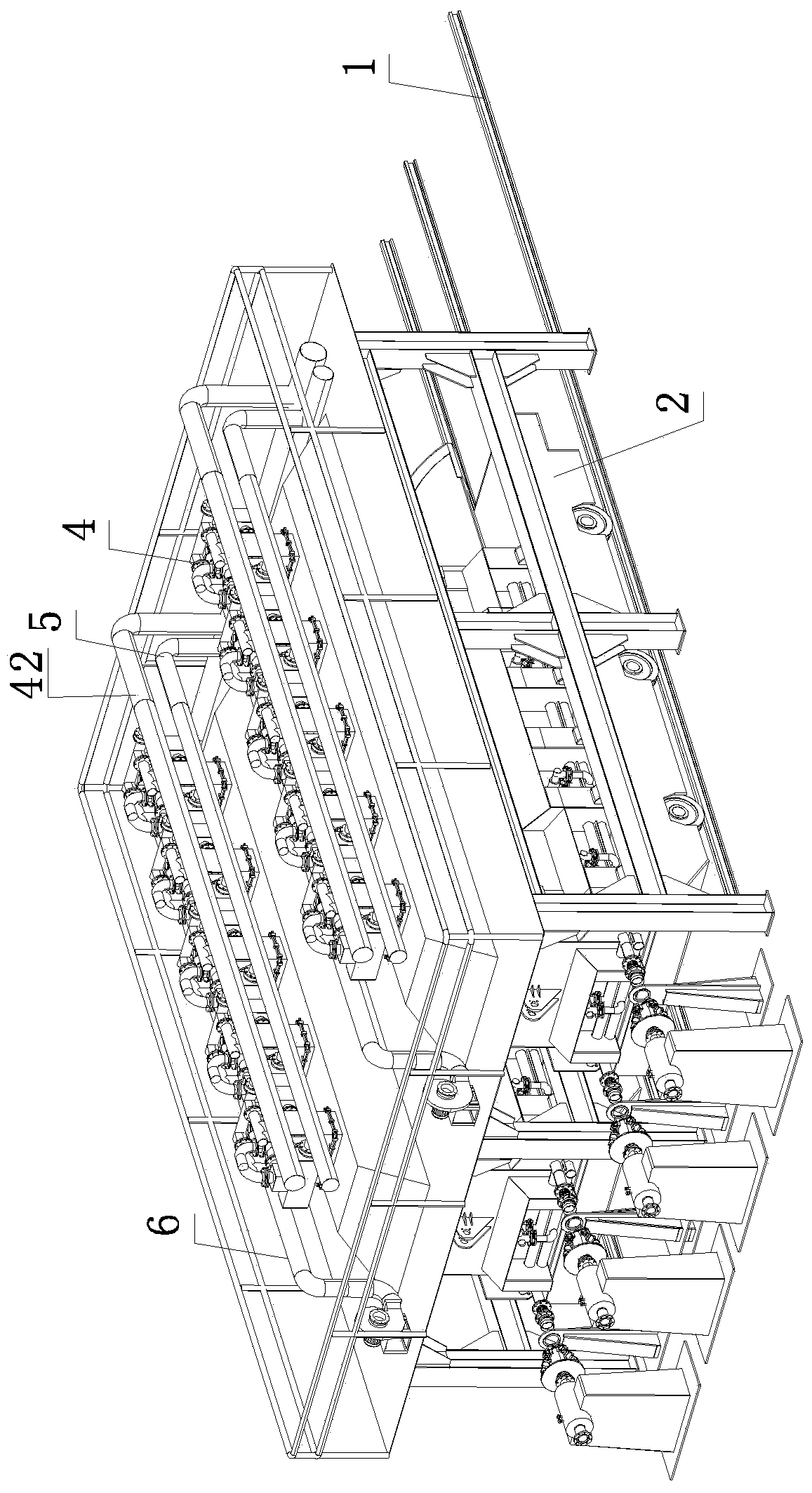
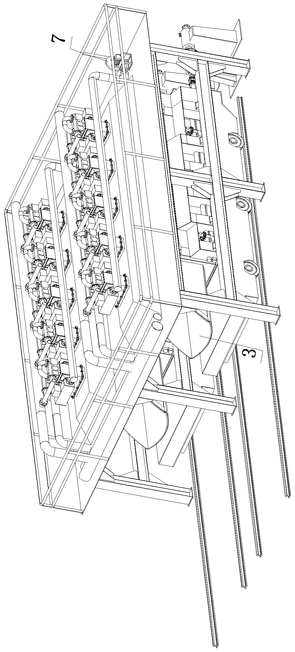
[0048] by figure 1 and figure 2 As an example, the scrap steel baking system of the present invention includes one or more sets of scrap steel preheating units arranged side by side in parallel. A double-layer composite heating bucket 3 with an open top for holding scrap steel on a mobile trolley, and multiple top burners 4 located above the double-layer composite heating bucket when installed on the frame platform for preheating; the frame The platform is also provided with a top floor gas pipeline 5, a top floor air pipeline 6 and a fan 7 connected to the top floor air pipeline for ...


PUM


Abstract

The invention relates to a steel scrap baking system. The system comprises one or multiple steel scrap preheating units arranged in parallel side by side. Each steel scrap preheating unit comprises arail, a moving trolley sliding along the rail, a dual-layer composite heating ship bucket arranged on the moving trolley, and multiple top layer combustors arranged on a rack platform; each heating ship bucket comprises an inner layer steel plate, an outer layer steel plate and refractory matter cast between the inner layer steel plate and the outer layer steel plate, one end of each ship bucket is opened and used for discharging, the other end of each ship bucket is closed, a tail combustor is arranged on each outer layer steel plate, the two side faces of each ship bucket are each provided with multiple side face combustors, three side faces surrounding the outer layer steel plate of each ship bucket are provided with U gas pipelines and U air pipelines, and the U gas pipelines and the Uair pipelines communicate with the outer air source through quick-change connectors. The system is reasonable in structural arranging, novel in type, high in adaptation, and high in work efficiency,cost is reduced, use needs are met, and the system is efficient and practical.

Description

technical field [0001] The invention belongs to the technical field of scrap steel baking, in particular to a scrap steel baking system. Background technique [0002] In iron and steel production, in order to save energy and reduce consumption, it is usually necessary to preheat scrap steel. In terms of economic benefits, on the one hand, scrap steel preheating can greatly reduce the energy consumption of the converter. The reduction of maintenance costs, the increase of output, and the improvement of steel quality all contribute to different degrees, and the comprehensive economic benefits are huge. Industrial enterprises are large energy consumers. The reduction of energy consumption can greatly reduce the emission of greenhouse gases and other nitrogen oxides, which has a positive impact on environmental governance and has obvious social benefits. [0003] The existing scrap steel preheating system has a single setting form, and the burner setting structure is unreasonab...

Claims


Application Information

Patent Timeline
IPC IPC(8): C21C5/56
CPCY02P10/20
Inventor 张会强
Owner LUOYANG WODA MACHINERY TECH DEV
Why Eureka
Try Eureka