
Capacitor clamp

A technology for capacitors and fixtures, applied in capacitors, capacitor manufacturing, circuits, etc., can solve problems such as failure to ensure good contact between capacitors and charging wires, reduced accuracy and stability of sheath wires, and inability to realize automated production. Workload, improved stability and accuracy, simple structure

Inactive Publication Date: 2014-04-23
广州市番禺桂博自动化设备制造厂
View PDF4 Cites 3 Cited by
  • Summary
  • Abstract
  • Description
  • Claims
  • Application Information

AI Technical Summary

Problems solved by technology

[0002] The factories that produce sheathed wire capacitors manually insert the sheathed wire capacitors and manually cut the materials when testing such capacitors, which cannot realize automated production, and manual insertion requires a lot of effort and labor intensity. , low production efficiency
At the same time, the manual plugging method cannot ensure good contact between the capacitor and the charging wire, resulting in a decrease in the accuracy and stability of the sheathed wire capacitance detection
[0003] Although some factories currently have some semi-automatic sheathed wire capacitor charging machines, they still remain in the semi-automatic production mode that requires manual auxiliary loading and unloading. The production efficiency is low, the labor intensity is high, and the production cost remains high.

Method used


Image

  • Capacitor clamp
  • Capacitor clamp

Examples


Embodiment Construction

[0022] Embodiments of the present invention are described in detail below:

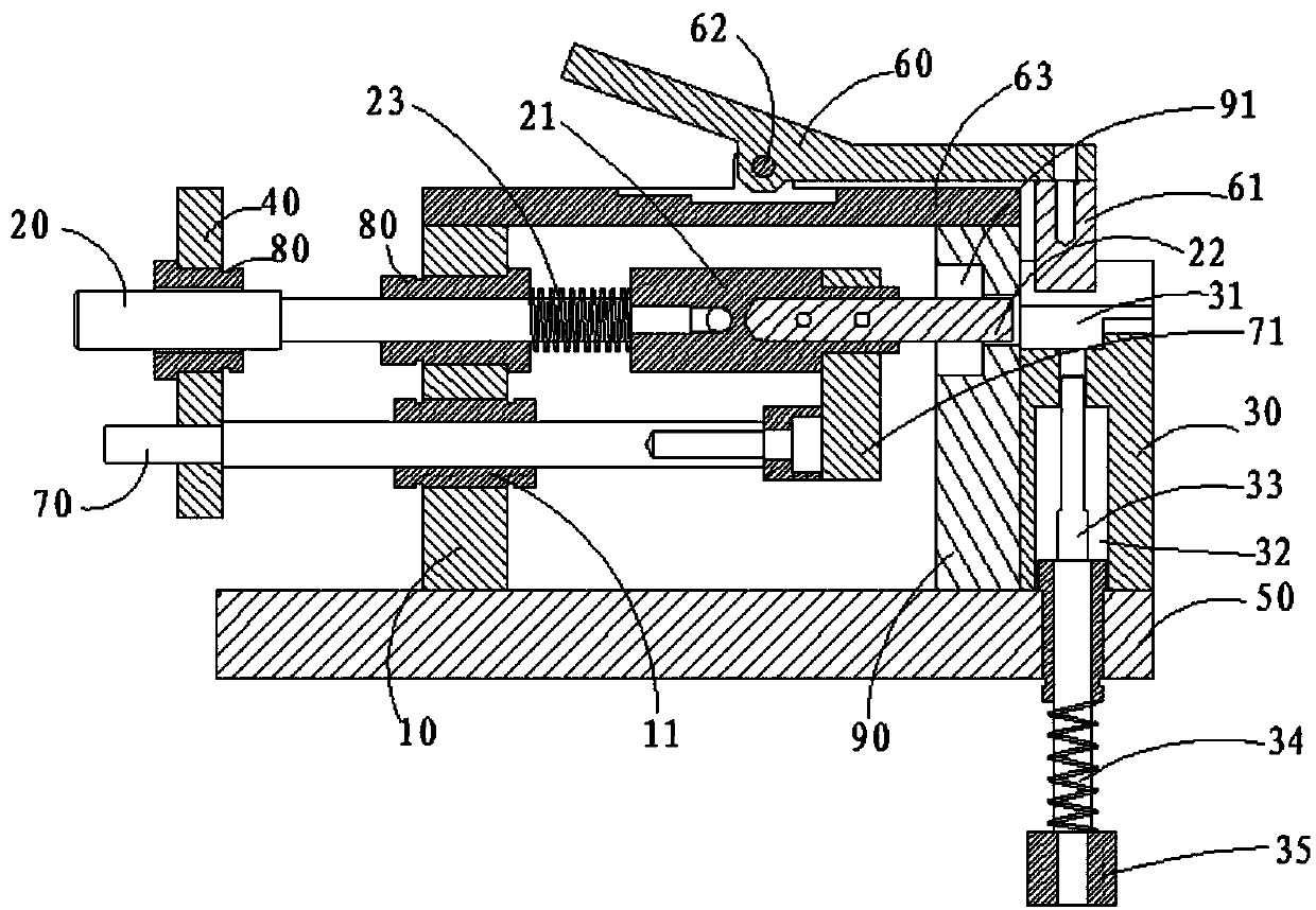
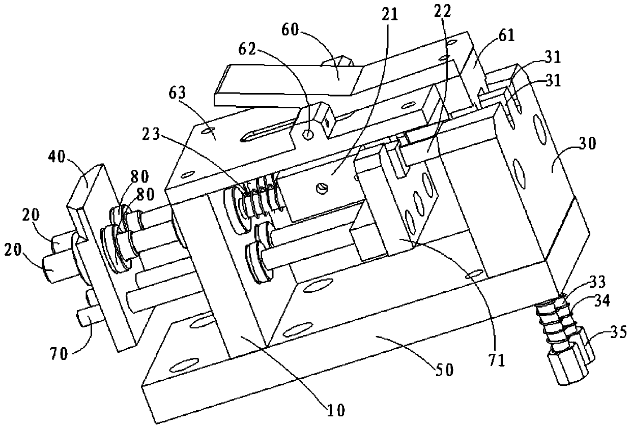
[0023] Such as figure 1 As shown, a capacitor fixture according to the present invention includes two conductive rods 20 and a first support plate 10. The first support plate 10 is provided with a first through hole for socketing the two conductive rods. Each conductive rod 20 is fixedly connected with a pull block 40, and also includes a lead end placement block 31, the lead end placement block 31 is provided with a lead end placement slot 31 corresponding to the first through hole, and the lead end placement slot 31 There are two, which are used to clip the charging terminal of the capacitor lead terminal.

[0024] Clamp the lead wire charging end of the sheath wire capacitor in the lead wire end placement groove 31, use a cylinder or hand to push the puller 40, and the pull block 40 drives the conductive rod 20 to electrically connect with the lead wire charging end of the sheath wire capacitor, t...


PUM


Abstract

The invention discloses a capacitor clamp. The capacitor clamp comprises two conductive rods, a first supporting plate and a lead terminal placement block, wherein the first supporting plate is provided with two first through holes for sleeving the two conductive rods; the two conductive rods are fixedly connected with pull bocks; the lead terminal placement block is provided with lead terminal placement grooves corresponding to the first through holes. Good contact of a capacitor in a detection process is guaranteed; the electrifying performance is stable; the detection stability and the detection accuracy of capacitors are greatly improved. The capacitor clamp is simple in structure, attractive in appearance, practical and low in cost.

Description

technical field [0001] The invention relates to a capacitor clamp. Background technique [0002] The factories that produce sheathed wire capacitors manually insert the sheathed wire capacitors and manually cut the materials when testing such capacitors, which cannot realize automated production, and manual insertion requires a lot of effort and labor intensity. , Low production efficiency. At the same time, the manual plug-in method cannot ensure good contact between the capacitor and the charging wire, which reduces the accuracy and stability of the sheathed wire capacitance detection. [0003] Although some factories currently have some semi-automatic capacitor charging machines for sheathed wires, they still remain in the semi-automatic production mode that requires manual auxiliary loading and unloading. The production efficiency is low, the labor intensity is high, and the production cost remains high. Contents of the invention [0004] Based on this, the present i...

Claims


Application Information

Patent Timeline
IPC IPC(8): H01G13/00G01R1/04
Inventor 蒋永官
Owner 广州市番禺桂博自动化设备制造厂
Features
  • Generate Ideas
  • Intellectual Property
  • Life Sciences
  • Materials
  • Tech Scout
  • Unparalleled Data Quality
  • Higher Quality Content
  • 60% Fewer Hallucinations
Learn More