Method for suppressing harmonic wave of interference signal based on electromagnetic compatibility

A technology for suppressing interference signals and harmonics, applied in harmonic reduction devices and AC networks to reduce harmonics/ripples, etc., can solve problems such as difficult implementation, limited suppression effect, and inability to reduce harmonic components, etc., to achieve easy Realization, harmonic suppression cost is low, and the effect of improving the harmonic suppression effect

Active Publication Date: 2014-04-23
苏州泰思特电子科技有限公司
View PDF3 Cites 4 Cited by
  • Summary
  • Abstract
  • Description
  • Claims
  • Application Information

AI Technical Summary

Problems solved by technology

Harmonic suppression of interference signals needs to start with quantization noise. The current quantization noise suppression methods mainly include oversampling, high-frequency dithering and other methods. Although the former reduces the average quantization noise power on the unit frequency band, it cannot reduce the harmonic components. ; Although the latter can suppress harmonics, it needs to add higher frequency noise to the collected signal through an analog circuit before digital collection, not only the suppression effect is limited but also difficult to implement in the actual electromagnetic compatibility test

Method used


Image

  • Method for suppressing harmonic wave of interference signal based on electromagnetic compatibility
  • Method for suppressing harmonic wave of interference signal based on electromagnetic compatibility
  • Method for suppressing harmonic wave of interference signal based on electromagnetic compatibility

Examples


Embodiment 1

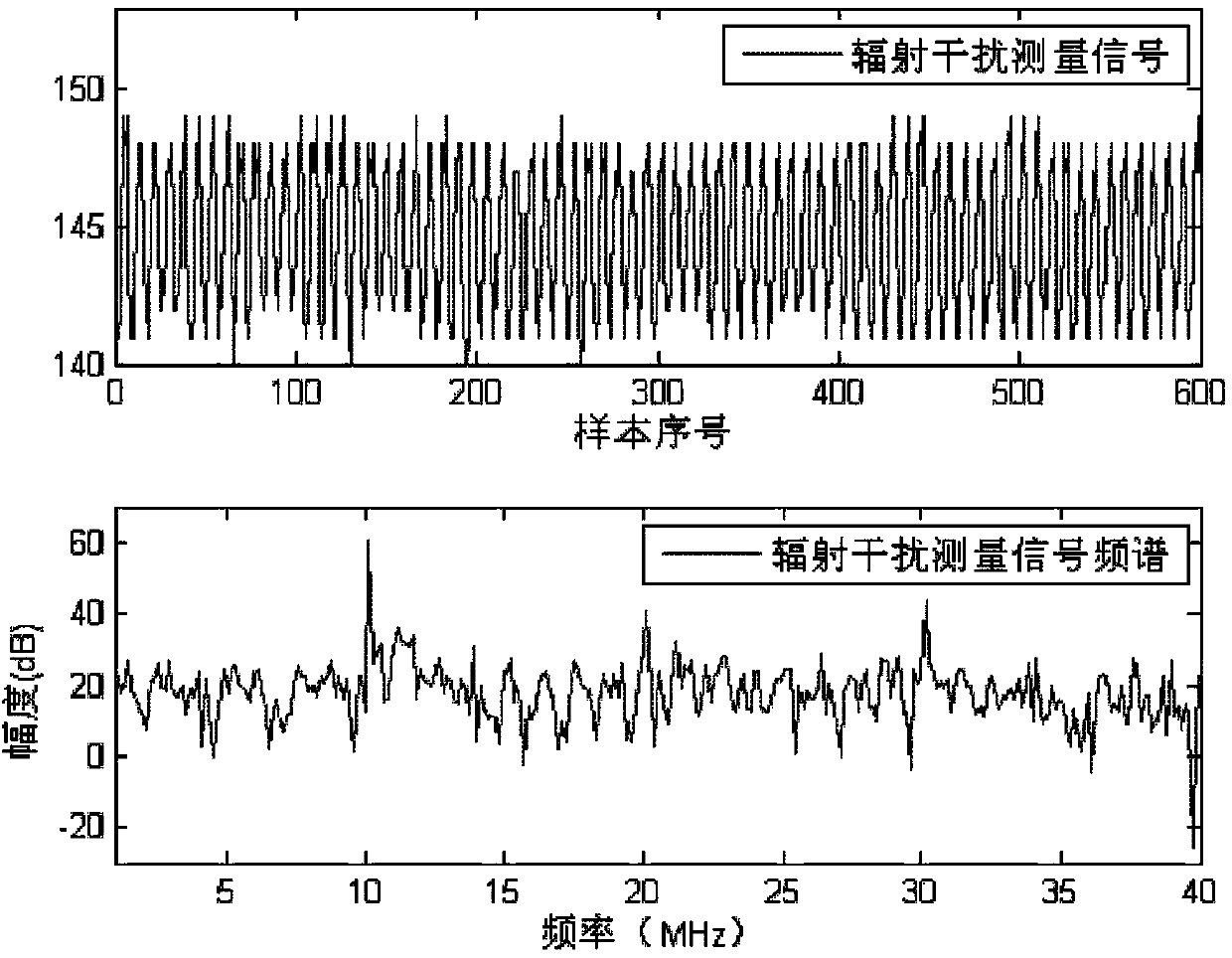
[0039] Embodiment 1: For the example of the harmonic suppression of radiated electromagnetic compatibility analysis interference signal, the product includes a 10MHz crystal oscillator, collects the radiated interference signal x(n) and its spectrum X(k) of this product with 80MHz sampling rate as figure 1 shown, visible figure 1 The middle frequency spectrum contains the radiated interference signal and its harmonics generated by the 10MHz crystal oscillator.

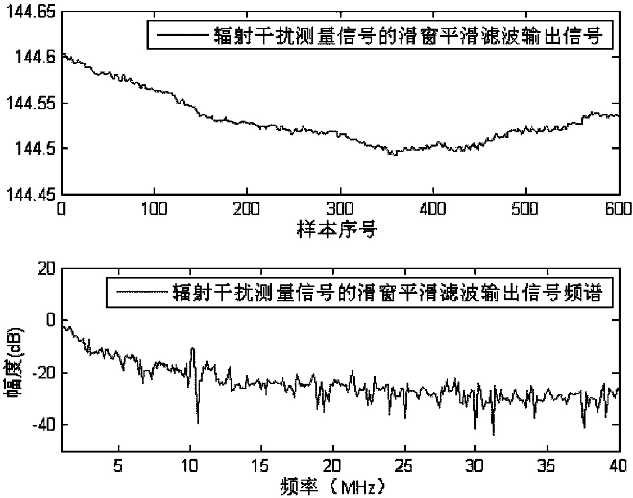
[0040] Step 1: The measured interference signal is averaged through the sliding window to suppress the quantization noise that causes harmonics, and obtain the corresponding smoothing filter signal spectrum, such as figure 2 As shown, the sliding window smoothing filter output signal w(n) and its spectrum W(k) of the interference signal x(n) are given by figure 2 It can be seen that the harmonics of the 10MHz signal in the smoothing filter output signal are greatly weakened, and the 10MHz radiation interference sign...

Embodiment 2

[0043] Embodiment 2: Example of harmonic suppression of interference signal in conducted electromagnetic compatibility analysis. In this conducted electromagnetic compatibility analysis, the product includes 2 crystal oscillators of 2.5MHz and 3.87MHz, and the common-mode conducted interference signal x( n) and its spectrum X(k) such as Figure 4 shown, visible Figure 4 Contains 2.5MHz and 3.87MHz conduction interference signals and their harmonics generated by 2 crystal oscillators.

[0044] Step 1: The measured interference signal is averaged through the sliding window to suppress the quantization noise that causes harmonics, and obtain the corresponding smoothing filter signal spectrum, such as Figure 5 As shown, the sliding window smoothing filter output signal w(n) of the interference signal x(n) and its spectrum W(k), it can be seen that the harmonics in the smoothing output signal are effectively attenuated, but the interference signal also becomes blurred, weak.

...


PUM


Abstract

The invention discloses a method for suppressing a harmonic wave of an interference signal based on the electromagnetic compatibility and belongs to the field of electromagnetic compatibility. The method comprises steps that an interference measuring signal to be analyzed is firstly subjected to sliding window average to suppress quantized nose causing the harmonic wave, a frequency spectrum of a corresponding smooth filtering signal is obtained, and then the smooth frequency spectrum carries out weighted correction on a frequency spectrum of the measuring signal, so that the harmonic wave of the interference measuring signal is suppressed. The method only utilizes the interference measuring signal to suppress harmonic wave noise without requiring other measurement or equipment, and the method is easy to carry out.

Description

Technical field: [0001] The invention relates to the technical field of electromagnetic compatibility, in particular to an electromagnetic compatibility-based harmonic suppression method for interference signals. Background technique: [0002] With the advancement of technology, more and more electronic products are required to meet the electromagnetic compatibility standards in China. If the interference caused by the electronic products to the environment during operation fails to meet the relevant electromagnetic compatibility standards, then the product should be tested before it enters the market. Carry out electromagnetic compatibility rectification until it reaches the standard. The key to rectification is to find out the source of exceeding the standard by analyzing the interference signal. However, due to the high cost, most electronic product manufacturers do not have high-performance test equipment; and the storage space of data acquisition equipment such as oscil...

Claims


Application Information

Patent Timeline
Patent Type & Authority Applications(China)
IPC IPC(8): H02J3/01
CPCY02E40/40
Inventor 赵阳邱晓晖黄学军
Owner 苏州泰思特电子科技有限公司
Why Eureka
Try Eureka