Magnetic driving mechanism and receiver

A technology of magnetic drive and receiver, which is applied in the direction of handset/headphone accessories, etc., can solve the problems of high difficulty in manufacturing process, small spacing, and the inability of the diaphragm to continue to vibrate, so as to achieve the effect of self-protection

Inactive Publication Date: 2014-04-23
SUZHOU YICHUAN TECH CO LTD
View PDF6 Cites 12 Cited by
  • Summary
  • Abstract
  • Description
  • Claims
  • Application Information

AI Technical Summary

Problems solved by technology

[0002] The armature is an important part of the drive device in the receiver. It drives the diaphragm in the receiver to vibrate through its own vibration to transmit sound. If the armature is subjected to a large impact, the armature will easily be sucked upward or downward by the magnet, which will cause the armature to fail to vibrate and make it invalid, so that the diaphragm will not continue to vibrate, so that the entire receiver cannot be normal. engineering work
[0003] In order to avoid the above situation, the traditional earphones generally use a raised part on the armature to prevent the armature from being integrated with the magnet. Although such a setting can achieve Very good effect, but because the distance between the magnet and the armature is small, its manufacturing process is difficult; and it is easy to reduce the vibration amplitude of the armature, and the audio range of the receiver will also become smaller, affecting the overall sound quality effect

Method used


Image

  • Magnetic driving mechanism and receiver
  • Magnetic driving mechanism and receiver
  • Magnetic driving mechanism and receiver

Examples


Embodiment 1

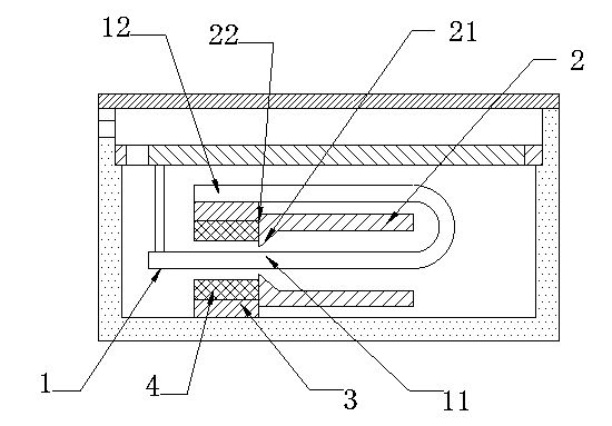
[0027] Such as figure 1 As shown, a receiver includes a magnetic drive mechanism. The magnetic drive mechanism includes a U-shaped armature 1, a coil 2 and an iron core 3. The U-shaped armature 1 includes a fixed part 12 and a vibration transducing part 11. The coil 2 and the iron core The core 3 is sleeved in the vibration transducing part 11 in turn, and the upper and lower sides of the vibration transducing part 11 are respectively provided with permanent magnets 4 fixedly connected to the inner surface of the iron core 3; the coil 2 is bonded to the iron core 3 to form a bond surface 22, the inner cavity of the coil 2 close to the adhesive surface 22 extends toward the vibration transducing part 11 to form a protruding part 21, and the distance between the protruding part 21 and the vibration transducing part 11 is smaller than the distance between the permanent magnet 4 and the vibration transducing part 11 The distance between the protrusions 21 and the coil 2 are integr...

Embodiment 2

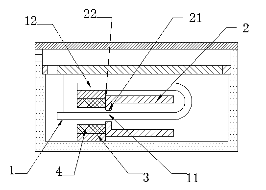
[0031] All the other are identical with embodiment 1, and difference is, as figure 2 As shown, the protruding part 21 of the coil 2 is a plane with respect to the surface of the vibration transducing part 11 .

[0032] Setting the surface of the protruding portion 21 relative to the vibration transducing portion 11 as a plane can effectively prevent the protruding portion 21 of the coil 2 from contacting the vibration transducing portion 11 of the armature 1 and causing damage to the armature due to the small contact surface. deformation.

[0033] Example 2

[0034] All the other are identical with embodiment 1, and difference is, as figure 2 As shown, the protruding part 21 of the coil 2 is a plane with respect to the surface of the vibration transducing part 11 .

[0035] Setting the surface of the protruding portion 21 relative to the vibration transducing portion 11 as a plane can effectively prevent the protruding portion 21 of the coil 2 from contacting the vibratio...

Embodiment 3

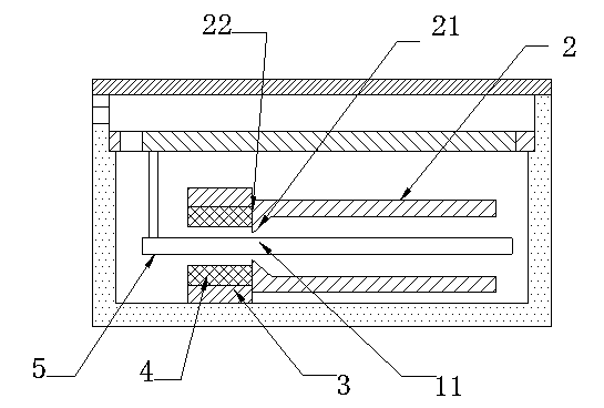
[0037] All the other are identical with embodiment 1, and difference is, as image 3 As shown, the armature 5 is an E-shaped armature, and the fixing portion 12 of the E-shaped armature 5 is fixedly connected to the outer surface of the iron core 3 .


PUM


Abstract

Provided is a magnetic driving mechanism which comprises an armature, a coil, and an iron core. The armature comprises a fixed portion and a vibration transduction portion. The coil and the iron core are successively sleeved on the vibration transduction portion. The top side and the bottom side of the vibration transduction portion are equipped with permanent magnets fixedly connected with the inner surface of the iron core. The coil and the iron core are bonded so as to form a bonded surface. The inner cavity of the coil close to the bonded surface is extended towards the vibration transduction portion to form a protruded portion. The distance between the protruded portion and the vibration transduction portion is less than the distance between the permanent magnet and the vibration transduction portion. The magnetic driving mechanism suitable for a receiver employs the coil provided with the protruded portion and may prevent the receiver from being attracted by the permanent magnets when the receiver is subjected to impact or the armature has overlarge vibration amplitude, wherein the receiver being attracted by the permanent magnets may result in the failure of the receiver. The invention also relates to a receiver containing the above magnetic driving mechanism.

Description

technical field [0001] The invention relates to a magnetic drive mechanism and a receiver. Background technique [0002] The armature is an important part of the drive device in the receiver. It drives the diaphragm in the receiver to vibrate through its own vibration to transmit sound. If the armature is subjected to a large impact, the armature will easily move upward or It is sucked down to the magnet, so that the armature cannot continue to vibrate and make it invalid, so that the diaphragm cannot continue to vibrate, so that the entire receiver cannot work properly. [0003] In order to avoid the above situation, traditional earphones generally use a raised part on the armature to prevent the armature from being integrated with the magnet. Although such a setting can achieve a good effect, due to the distance between the magnet and the armature Smaller, the manufacturing process is more difficult; and it is easy to reduce the vibration amplitude of the armature, and t...

Claims


Application Information

Patent Timeline
Patent Type & Authority Applications(China)
IPC IPC(8): H04R1/10
Inventor 周巍
Owner SUZHOU YICHUAN TECH CO LTD
Why Eureka
Try Eureka