Easy-to-mount computer case guide rail

A technology of guide rails and chassis, applied in the direction of rack/frame structure, etc., can solve the problems of troublesome disassembly, cumbersome manufacturing and installation procedures, and complicated structure of chassis guide rails, and achieve simple structure of chassis guide rails, convenient and fast installation, and good application prospects Effect

Inactive Publication Date: 2014-04-23
NANJING PANENG TECHNOLOGY DEVELOPMENT CO LTD
View PDF2 Cites 3 Cited by
  • Summary
  • Abstract
  • Description
  • Claims
  • Application Information

AI Technical Summary

Problems solved by technology

[0002] A guide rail is a device that bears, fixes, guides a mobile device or equipment and reduces its friction. There are many aspects of guide rails used in daily life, and there are various types of guide rails produced, such as chassis guide rails. At present, the guide rails of chassis such as figure 1 As shown, in order to facilitate the subsequent installation on the chassis profile with countersunk head screws, the chassis guide rail needs to be drilled and tapped during production. Screws install the chassis guide rails on the chassis profile, which is cumbersome to manufacture and install, and more troublesome to disassemble, which is not conducive to the replacement of the chassis guide rails
In addition, in order not to affect the guiding function of the chassis guide rail, but also to drill holes on the chassis guide rail, an additional protruding block 6 (such as figure 2 As shown), although this facilitates the installation of the chassis guide rail, it restricts the installation direction of the chassis guide rail on the chassis profile. In order to avoid interference between the chassis guide rail and the shielding plate 7, the chassis guide rail can only be placed in a fixed position and a fixed direction. Facilitate the multi-directional use of chassis rails
In addition, the structure of the chassis guide rails currently used is relatively cumbersome, so further optimization is required

Method used


Image

  • Easy-to-mount computer case guide rail
  • Easy-to-mount computer case guide rail
  • Easy-to-mount computer case guide rail

Examples


Embodiment Construction

[0019] The present invention will be further described below in conjunction with the accompanying drawings.

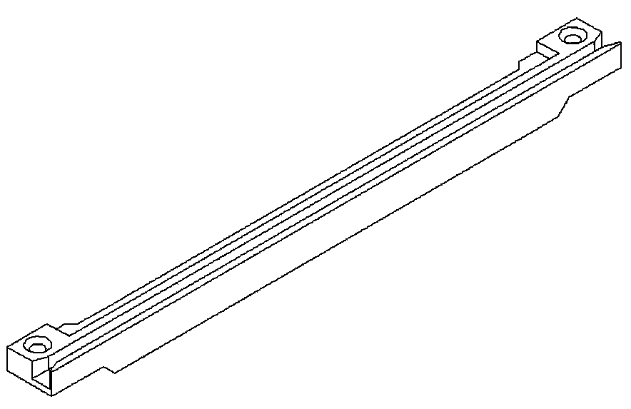
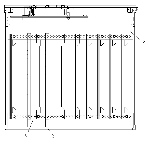
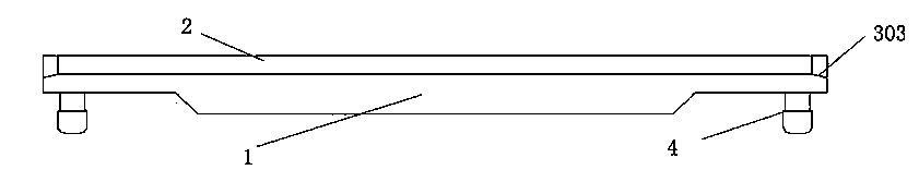
[0020] Such as Figure 3 to Figure 6 As shown, an easy-to-install chassis guide rail includes a guide rail body 1. A groove 2 is provided inside the guide rail body 1 along the length direction of the guide rail body 1. The groove 2 provides guidance for the insertion of subsequent printed boards, namely The printed board moves along the length direction of the guide rail body 1. In order to facilitate the subsequent printed board to enter the groove 2 smoothly, guide surfaces 3 are provided at both ends of the groove 2. In detail, the guide surface 3 includes The first guide surface 301 connected to the two sides of the groove 2, the second guide surface 302 and the third guide surface 303 connected to the bottom surface of the groove 2, the first guide surface 301, the second guide surface 302 and the third guide surface 303 are slopes formed by slanting. The first ...


PUM


Abstract

The invention discloses an easy-to-mount computer case guide rail, comprising a guide rail body, wherein the guide rail body is internally provided with a groove along the length direction of the guide rail body, the two ends of the groove are provided with a guiding surface respectively, the lower sides of the two ends of the guide rail body are provided with plugs, each plug comprises a fixing part and a guiding part, one end of each fixing part is connected with the lower side of the guide rail body, the other end of each fixing part is connected with the upper side of the corresponding guiding part, and the end, not connected with the corresponding fixing part, of each guiding part is in a circular arc shape. The easy-to-mount computer case guide rail provided by the invention is simple in structure, convenient to manufacture and fast in mounting and detaching, facilitates position replacement of the computer case guide rail, cannot generate interference with a shielding plate and has good application prospect.

Description

technical field [0001] The invention belongs to the field of guide rail structures, and in particular relates to an easy-to-install cabinet guide rail. Background technique [0002] A guide rail is a device that bears, fixes, guides a mobile device or equipment and reduces its friction. There are many aspects of guide rails used in daily life, and there are various types of guide rails produced, such as chassis guide rails. At present, the guide rails of chassis such as figure 1 As shown, in order to facilitate the subsequent installation on the chassis profile with countersunk head screws, the chassis guide rail needs to be drilled and tapped during production. Screws install the chassis guide rails on the chassis profiles, so the manufacturing and installation procedures are relatively cumbersome, and the disassembly is troublesome, which is not conducive to the replacement of the chassis guide rails. In addition, in order not to affect the guiding function of the chassis...

Claims


Application Information

Patent Timeline
Patent Type & Authority Applications(China)
IPC IPC(8): H05K7/18
Inventor 贾海军
Owner NANJING PANENG TECHNOLOGY DEVELOPMENT CO LTD
Why Eureka
Try Eureka