
multi-component cartridge

A multi-component, two-component technology, used in dispensing devices, containers with multiple items, packaging, etc., can solve problems such as huge changes, and achieve the effect of reducing the risk of cross-contamination

Active Publication Date: 2016-04-20
MEDMIX SWITZERLAND AG
View PDF5 Cites 0 Cited by
  • Summary
  • Abstract
  • Description
  • Claims
  • Application Information

AI Technical Summary

Problems solved by technology

This results in the 1500 ml two-component cartridge varying greatly in its external dimensions for different mixing ratios of the components

Method used


Image

  • multi-component cartridge
  • multi-component cartridge
  • multi-component cartridge

Examples


Embodiment Construction

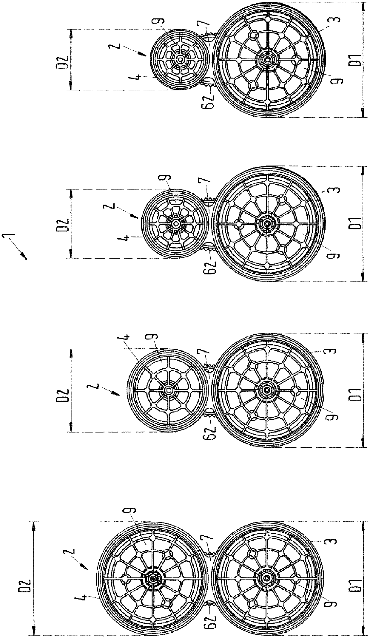
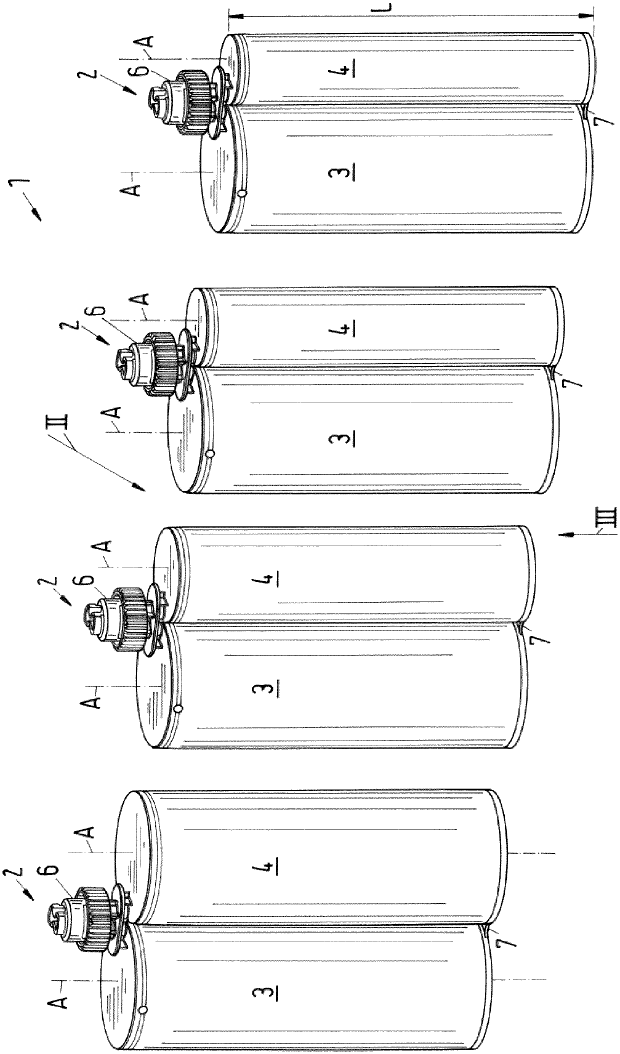
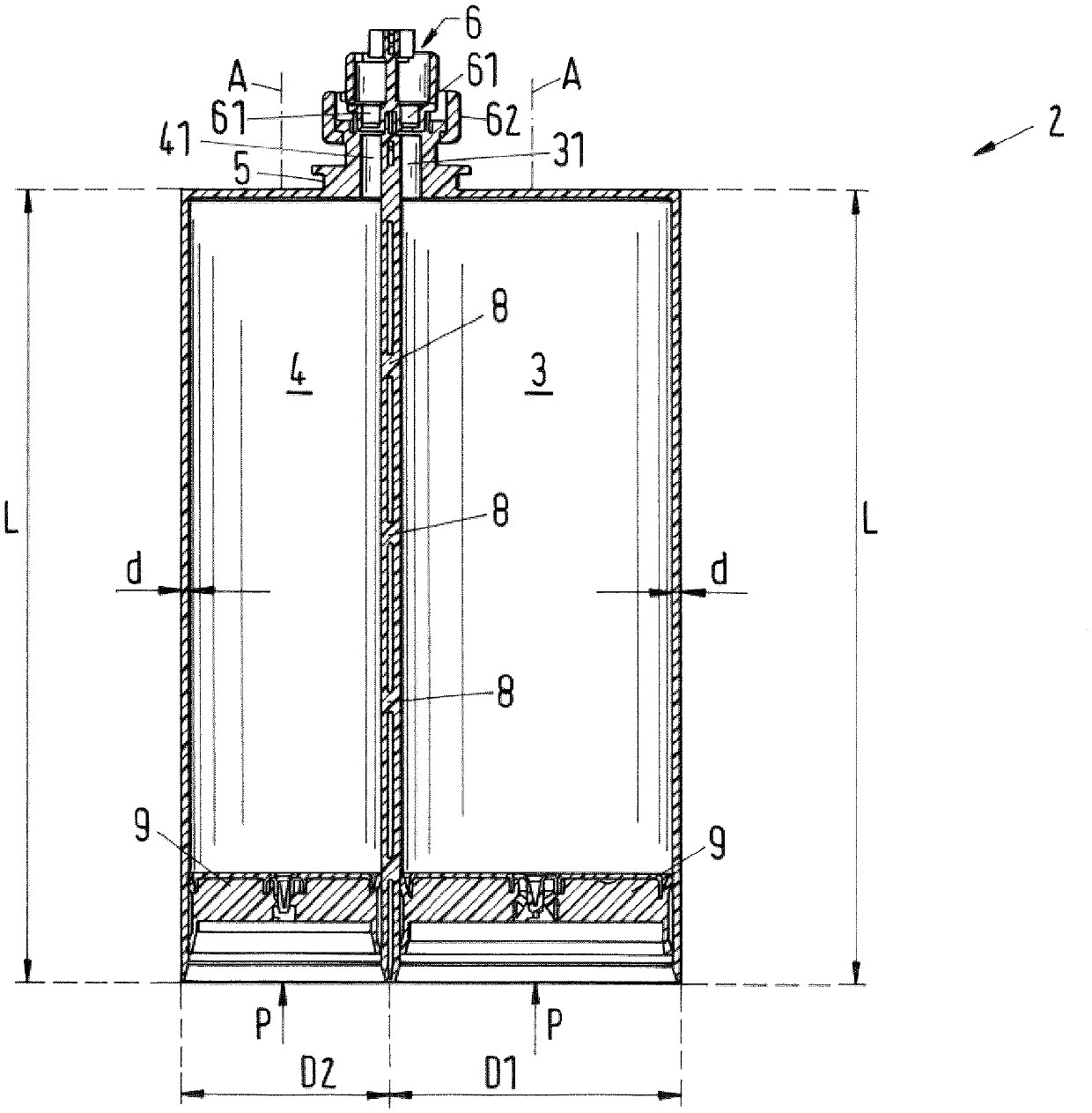
[0031] figure 1 A perspective view of an exemplary embodiment of a multi-component cartridge set according to the invention is shown, which is generally designated with the reference numeral 1 and here includes four multi-component cartridges 2 .

[0032]Reference is made below with exemplary features to the application which is particularly important for practice, namely that the multi-component cartridge 2 is correspondingly a two-component cartridge 2 . However, it is understood that the invention is not restricted to such a configuration, but can also include multicomponent cartridges 2 for more than two components in the same manner.

[0033] figure 2 show figure 1 From the barrel group 1 figure 1 The view seen in the direction indicated by arrow II.

[0034] image 3 A view looking towards the bottom of the multi-component cartridge 2 is shown, ie from image 3 The view looking in the direction indicated by arrow III.

[0035] For better understanding, Figure 4...


PUM


Abstract

The invention relates to a cartridge set consisting of multicomponent cartridges, having at least two multicomponent cartridges (2), wherein each multicomponent cartridge (2) comprises at least one second cartridge for the component to be discharged. A receiving chamber and a second receiving chamber (3, 4), wherein each receiving chamber (3, 4) is configured substantially cylindrically and extends along the longitudinal direction (A), wherein the receiving chambers (3, 4 ) are arranged parallel to each other and have the same extent (L) in the longitudinal direction (A), wherein each multicomponent cartridge (2) is made in one piece so that its receiving chambers (3, 4) are non-detachable from each other connected, and wherein the first accommodation chambers (3) of each multi-component cartridge (2) of the cartridge set (1) have the same outer diameter (D1).

Description

technical field [0001] The invention relates to a multicomponent cartridge set with at least two multicomponent cartridges according to the preambles of the independent claims. Background technique [0002] Multi-component cartridges and especially two-component cartridges are frequently used for storage and for discharging multi-component or two-component systems in which the individual components are only Only the corresponding uses come into contact with each other for subsequent age hardening, for example. For this purpose, two or more separate holding chambers are provided, each of which contains one of the components. For this purpose, the outlets of the holding chambers are then typically connected to a static mixer and the components are passed through by applying pressure to the rear bottom of the respective holding chamber (usually designed as a movable piston). The discharge port leads into a mixer where the components are mixed deeply enough to then flow out as...

Claims


Application Information

Patent Timeline
Patent Type & Authority Patents(China)
IPC IPC(8): B65D81/32
CPCB65D81/325B65D81/3283B65D81/3288B65D83/0005B65D1/04B65D25/38
Inventor S.哈比比-奈尼M.谢尤伯
Owner MEDMIX SWITZERLAND AG
Learn More