Locating shaft for forming incisions

A technology for positioning shafts and cutting marks, which is applied in metal processing and other directions

Inactive Publication Date: 2014-04-30
CHONGQING JIANWEI MACHINERY
View PDF0 Cites 4 Cited by
  • Summary
  • Abstract
  • Description
  • Claims
  • Application Information

AI Technical Summary

Problems solved by technology

[0003] The invention provides a positioning shaft for forming cut marks to solve the problem that the existing indentations need to be formed by cutting knives

Method used


Image

  • Locating shaft for forming incisions

Examples


Embodiment Construction

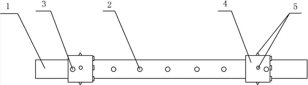
[0009] Such as figure 1 As shown, a positioning shaft for forming cut marks in this embodiment includes a positioning shaft body 1, and seven adjustment holes 2 are arranged on the positioning shaft body 1 along the axial direction, and connecting holes are provided on the shaft sleeve 4. A latch 3 is provided between the adjustment hole 2 and the connection hole, and a shaft sleeve 4 is sleeved on the positioning shaft body 1 . The shaft sleeve 4 is provided with a needle body 5 along the circumference of the positioning shaft body 1, the needle body 5 is divided into a needle head and a needle seat, the needle head faces the outer wall of the shaft sleeve 4, and the needle seat and the shaft sleeve 4 are connected by a spring.

[0010] Next, the working mode of this embodiment is described by taking the cut mark of the packaging bag as an example. First, fix the two bushings 4 on the positioning shaft body 1, install the positioning shaft for forming the easy-tear opening on...


PUM


Abstract

The invention discloses a locating shaft for forming incisions. The locating shaft comprises a locating shaft body, wherein a shaft sleeve is sleeved on the locating shaft body; the shaft sleeve is provided with a needle body along the circumference of the locating shaft body; the needle body is divided into a needle head and a needle seat; the needle head faces to the outer side wall of the shaft sleeve; the needle seat and the shaft sleeve are connected through a spring. A special electric motor does not need to be arranged, and obligated intermission time is also not needed. The shaft sleeve is sleeved on the locating shaft body, the shaft sleeve is connected with the needle body, the needle body contacts with packaging bags or paper on a conveyor belt, and the conveyor belt drives the shaft sleeve to rotate, so that the incisions are formed. The needle body and the shaft sleeve are connected through the spring, and the height can be adjusted by oneself in the free deformation range of the spring so as to be suitable for the packaging bags or paper with different thicknesses.

Description

technical field [0001] The present invention belongs to the technical field of packages. Background technique [0002] In order to facilitate tearing, many packaging bags or paper products are equipped with cut marks. At present, the indentation is realized by the intermittent movement of the cutting knife, which requires a special motor to control the cutting knife. Not only does it need to reserve Intermittent time, and waste of cost, thereby increasing the cost of production. Contents of the invention [0003] The invention provides a positioning shaft for forming a cutting mark, so as to solve the problem that the existing indentation needs a cutting knife to form. [0004] In order to solve the above-mentioned technical problems, the present invention provides the following technical solutions: A positioning shaft for forming cut marks, comprising a positioning shaft body, a shaft sleeve is sleeved on the positioning shaft body, and the shaft sleeve is provided along...

Claims


Application Information

Patent Timeline
Patent Type & Authority Applications(China)
IPC IPC(8): B26D3/08B26D7/26
Inventor 江伟
Owner CHONGQING JIANWEI MACHINERY
Why Eureka
Try Eureka