Pressing device for inductance coil and copper foil films

A technology of inductance coil and pressing device, which is applied in the direction of inductance/transformer/magnet manufacturing, coil manufacturing, circuit, etc., which can solve the problems of unfavorable inductance coil processing process, increased economic burden of enterprises, and affecting the appearance of products, etc.

Pending Publication Date: 2021-09-03
YAXIN (HUAIHUA) ELECTRONICS CO LTD
View PDF0 Cites 0 Cited by
  • Summary
  • Abstract
  • Description
  • Claims
  • Application Information

AI Technical Summary

Problems solved by technology

[0004] At present, there are the following technical problems in the process of inductance coil processing: 1. It is necessary to feed the coiled copper foil raw materials. The traditional manual feeding device has technical problems such as difficult feeding, high labor intensity, and low labor efficiency. The turntable feeding structure also has a low load-carrying capacity, and it is difficult to adjust the height of the rolled copper foil material independently. In addition, during the rotating feeding process, the outer edge of the rolled copper foil material is prone to slipping and offset, which is not conducive to the inductance coil. Subsequent processing will affect the processing quality; 2. In the process of conveying the copper foil and film of the induction coil, the phenomenon that the copper foil and the film cannot be aligned often occurs, resulting in misalignment of the copper foil and the film on the induction coil, both It affects the processing quality of the product, causes an increase in the scrap rate, and seriously affects the appearance of the product, resulting in an increase in the economic burden of the enterprise; 3. In the process of winding the c

Method used


Image

  • Pressing device for inductance coil and copper foil films
  • Pressing device for inductance coil and copper foil films
  • Pressing device for inductance coil and copper foil films

Examples


Embodiment Construction

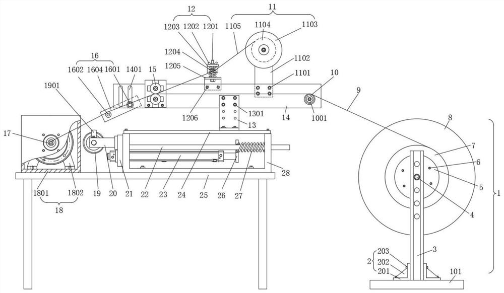
[0033] In order to enable those skilled in the art to better understand the technical solution of the present invention, the present invention will be described in detail below in conjunction with the accompanying drawings. The description in this part is only exemplary and explanatory, and should not have any limiting effect on the protection scope of the present invention. .

[0034] Such as Figure 1-Figure 10 Shown, the specific structure of the present invention is: comprise workbench 25 and fixed bracket 28, workbench 25 is provided with the workpiece support rod 17 that is used to place induction coil, one end of workpiece support rod 17 is arranged on the drive assembly 18, workpiece support rod 17 side ends and on the fixed bracket 28 side walls are provided with a movable plate body 21, the fixed frame 20 of the movable plate body 21 side ends is rotated to set the pressing pipe body 19, and the pressing pipe body 19 can touch the workpiece support rod 17 The induct...


PUM


Abstract

The invention discloses a pressing device for an inductance coil and copper foil films, and relates to the technical field of inductance coil processing. The device comprises a workbench and a fixed support, the workbench is provided with a workpiece supporting rod, one end of the workpiece supporting rod is arranged on a driving assembly, the side end of the workpiece supporting rod is provided with a movable plate body, a pressing pipe body is rotationally arranged in the fixed frame at the side end of the movable plate body, a frame blocking plate is arranged above the fixed frame, a connecting plate body is installed at the top of the fixed frame through an upper carrying plate, the connecting plate body is connected with a transverse plate body through a fourth screw, the transverse plate body is sequentially provided with an angle adjusting assembly used for attaching copper foil films, a cleaning assembly, a conveying assembly, a second feeding assembly and a first rotating cylinder, and a first feeding assembly is arranged on the side portion of the transverse plate body. A copper foil and a film can be prevented from loosening or shifting in the transportation process, pressing operation can be provided in the process of winding the copper foil and the film on an inductance coil, and the copper foil, the film and the inductance coil can be combined more tightly.

Description

technical field [0001] The invention relates to the technical field of inductance coil processing, in particular to a copper foil film pressing device for inductance coils. Background technique [0002] The inductance coil is a device that uses the principle of electromagnetic induction to work. When a current flows through a wire, a certain electromagnetic field will be generated around the wire, and the wire itself of this electromagnetic field will induce the wire in the range of this electromagnetic field, and the wire itself that generates the electromagnetic field The effect that occurs is called "self-inductance", that is, the changing current generated by the wire itself produces a changing magnetic field, and this magnetic field further affects the current in the wire; the effect on other wires in the range of this electromagnetic field is called "mutual inductance". The electrical characteristics of the inductance coil are opposite to those of the capacitor, "pass...

Claims


Application Information

Patent Timeline
IPC IPC(8): H01F41/04H01F41/082H01F41/096
CPCH01F41/04H01F41/096H01F41/082
Inventor 金代东
Owner YAXIN (HUAIHUA) ELECTRONICS CO LTD
Why Eureka
Try Eureka