
Three-dimensional inspection sample plate for taper milling cutter

A technology of taper and template, which is applied in the field of three-dimensional inspection templates of taper milling cutters, can solve the problems of difficult alignment of the tool tip point, difficulty of detecting the size of the bottom diameter of the tool, and inaccurate alignment of the tool, so as to achieve convenient on-site operation and improve detection The effect of precision and simple structure design

Inactive Publication Date: 2014-04-30
CRRC ZIYANG CO LTD
View PDF5 Cites 1 Cited by
  • Summary
  • Abstract
  • Description
  • Claims
  • Application Information

AI Technical Summary

Problems solved by technology

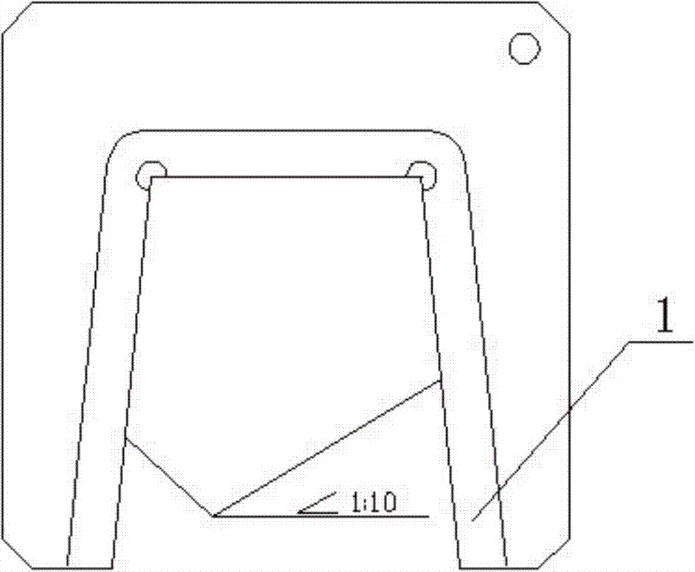
However, since the tool itself has a three-dimensional structure, and the tool inspection template is generally a thin plate with a thickness of t5, in actual inspection, the inspection template used cannot be accurately aligned with the diameter direction of the tool, and it is difficult to guarantee the detection accuracy of the tool; another On the one hand, because the blade of the tool is a spiral structure, even if the thin-plate detection template is aligned with the direction of the tool diameter, it is difficult to align the tool tip point (that is, the highest point of the tool), and it is also difficult to detect the bottom diameter of the tool.
Therefore, the existing testing templates are extremely inconvenient in the actual testing process, and it is difficult to meet the requirements of testing whether the size of the tool to be used is qualified.

Method used


Image

  • Three-dimensional inspection sample plate for taper milling cutter
  • Three-dimensional inspection sample plate for taper milling cutter
  • Three-dimensional inspection sample plate for taper milling cutter

Examples


Embodiment Construction

[0016] In order to make the object, technical solution and advantages of the present invention clearer, the present invention will be described in detail below in conjunction with the accompanying drawings and specific embodiments. It should be understood that the specific embodiments described here are only used to explain the present invention, not to limit the present invention.

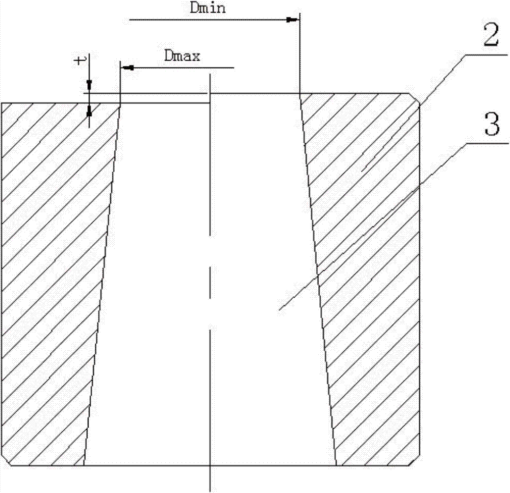
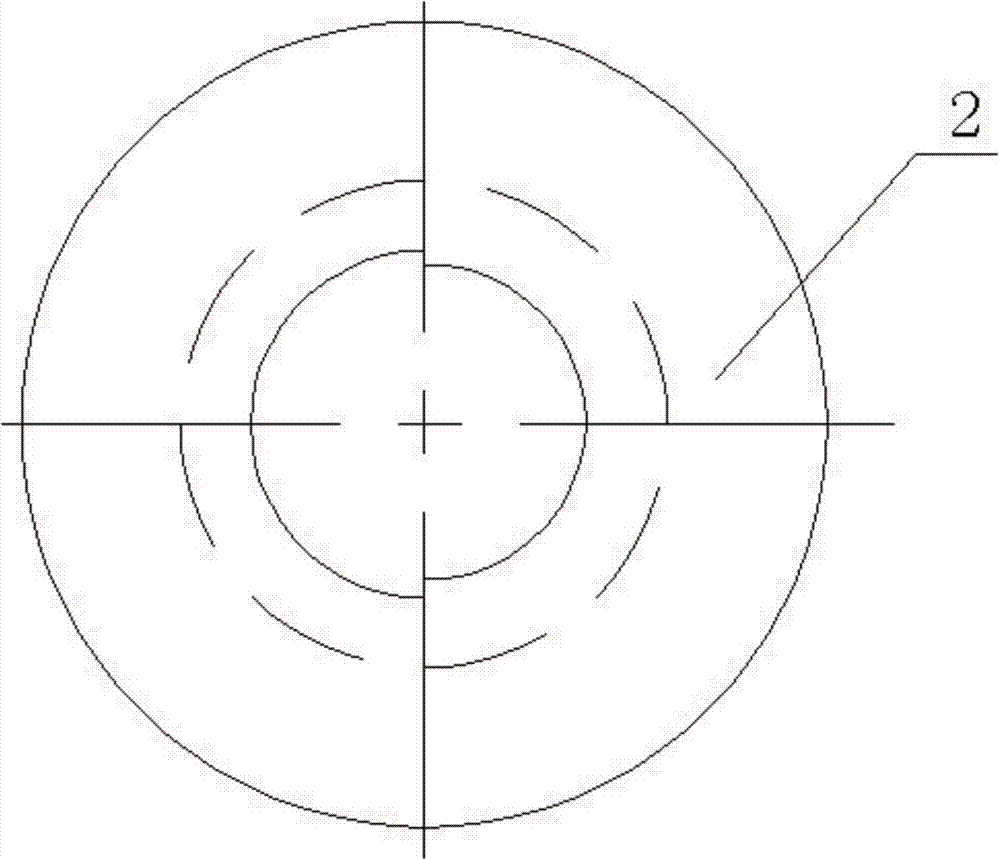
[0017] like Figure 2-Figure 4 The three-dimensional inspection template of a tapered milling cutter mainly includes a template main body 2 , and a taper hole 3 penetrating through the template main body 2 is opened on the template main body 2 .

[0018] In the following, a specific tapered milling cutter with a taper of 1:5 is taken as an example to describe in detail. The blade portion of the tapered milling cutter has a taper of 1:5, and the lower difference of the diameter tolerance of the circle where the tip point of the tapered milling cutter is located is Dmin , the upper difference of th...


PUM


Abstract

The invention provides a three-dimensional inspection sample plate for a taper milling cutter. A taper hole (3) penetrating through a sample plate body (2) is formed in the inspection sample plate, and the taper of the taper hole (3) is equal to that of a blade portion of the taper milling cutter. The diameter of the circumference of one side of the smaller end in the two ends of the taper hole (3) is equal to the lower tolerance of the diameter tolerance of the circumference where a tool nose point of the taper milling cutter is located, and the diameter of the circumference of the other side of the smaller end in the two ends of the taper hole (3) is equal to the upper tolerance of the diameter tolerance of the circumference where the tool nose point of the taper milling cutter is located. The height difference of the two sides of the smaller end in the two ends of the taper hole (3) is equal to the specific value between the difference value of the diameters of the circumferences on the two sides and the taper of the taper hole (3). According to the three-dimensional inspection sample plate, the problem that centering through an existing sheet type chute cutter inspection sample plate can not be achieved is effectively solved, inspection accuracy on cutters is improved, and the three-dimensional inspection sample plate has the obvious advantages of being simple in structure, convenient to operate on site, and the like.

Description

technical field [0001] The invention relates to the technical field of tapered milling cutter inspection, in particular to a three-dimensional inspection template for tapered milling cutters in mechanical processing. Background technique [0002] The current locomotive traction rod seat mostly adopts a tapered chute plus a bolt connection structure, wherein the chute of the tie rod seat is a tapered chute with a taper of 1:5. In the process of workpiece processing, a forming taper milling cutter is generally used for machining. However, due to the manufacturing accuracy and regrinding of the machining tool, the diameter of the bottom of this type of forming tool is different, resulting in different shapes and sizes of the chute processed by the tool, and the processing quality is difficult to control. Therefore, before processing, it is necessary to first check whether the overall dimensions of the tool used are qualified. [0003] In order to qualitatively detect the overa...

Claims


Application Information

Patent Timeline
Patent Type & Authority Applications(China)
IPC IPC(8): G01B5/08
Inventor 杨婕陈启彬赖凯
Owner CRRC ZIYANG CO LTD
Learn More