
Operating Mechanism Chassis Vehicle Interlocking Device and Interlocking Method

A technology of interlocking device and operating mechanism, which is applied to switch devices, pull-out switch cabinets, electrical components, etc., can solve the problems of complex interlocking structure of chassis vehicles, the failure of the mechanism to operate normally, and the influence of interlocking failure, etc. Easy debugging and maintenance, reliable interlocking, good stability

Active Publication Date: 2016-04-20
宁波剑润机电有限公司
View PDF8 Cites 0 Cited by
  • Summary
  • Abstract
  • Description
  • Claims
  • Application Information

AI Technical Summary

Problems solved by technology

[0003] In order to overcome the above disadvantages, the purpose of the present invention is to provide the field with an operating mechanism chassis interlocking device and its interlocking method, so that it can solve the problem of complex interlocking structures and increased errors in existing similar operating mechanisms. As a result, the failure of the interlock affects the internal operation of the mechanism, making the mechanism unable to operate normally.

Method used


Image

  • Operating Mechanism Chassis Vehicle Interlocking Device and Interlocking Method
  • Operating Mechanism Chassis Vehicle Interlocking Device and Interlocking Method
  • Operating Mechanism Chassis Vehicle Interlocking Device and Interlocking Method

Examples


Embodiment Construction

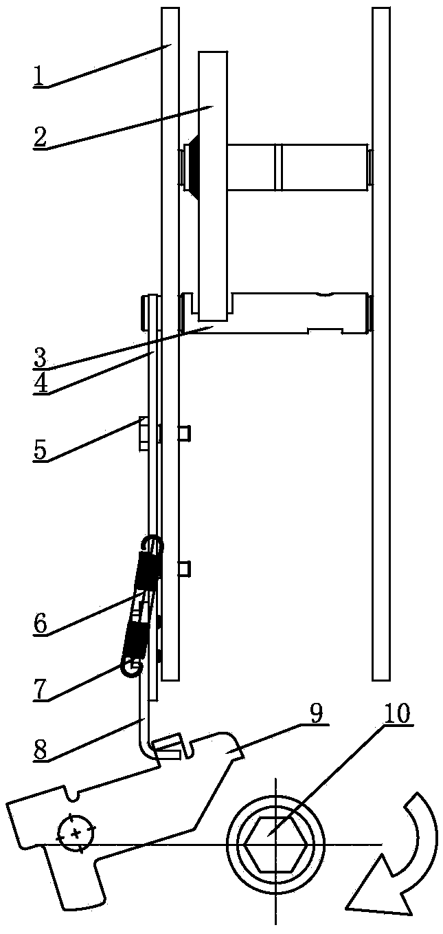
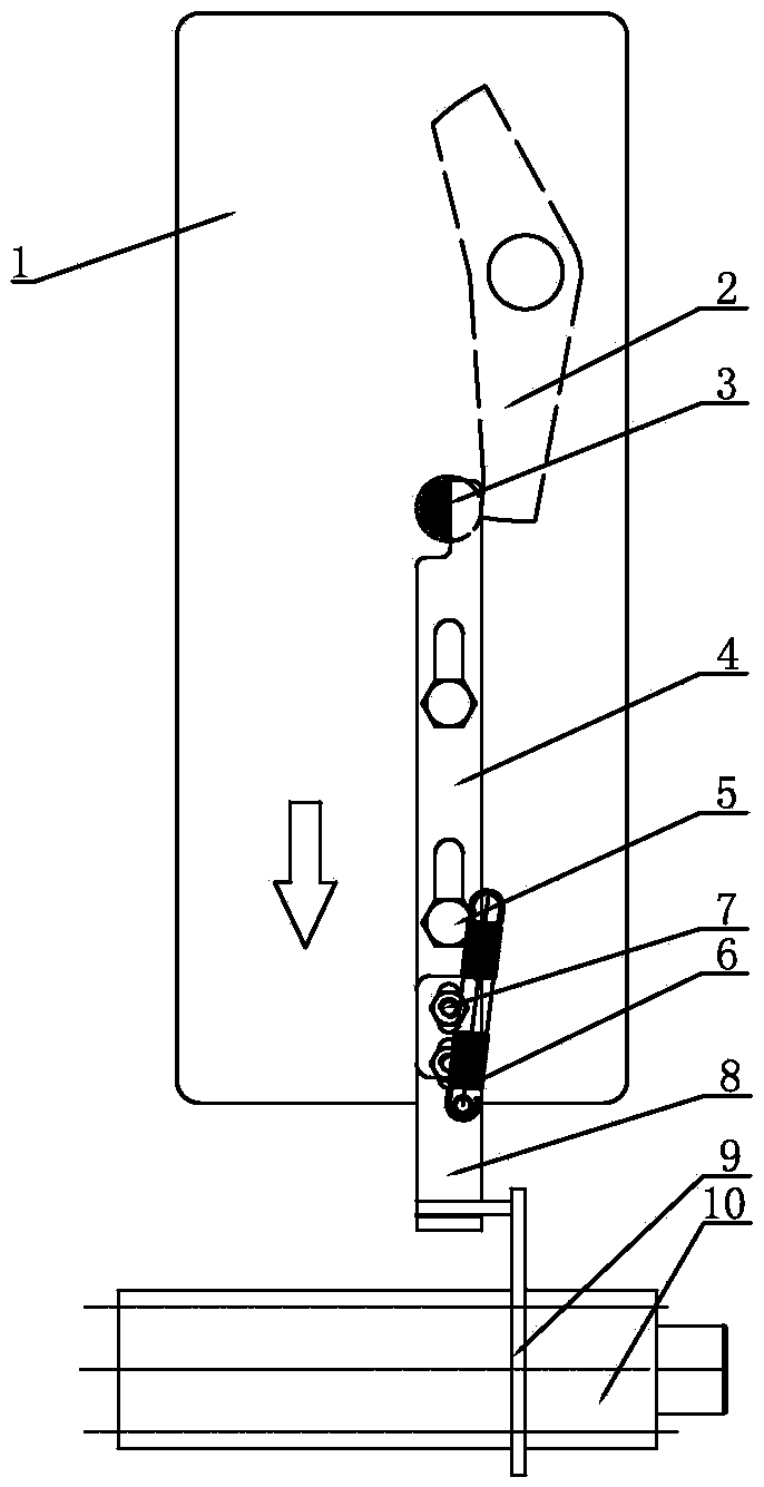
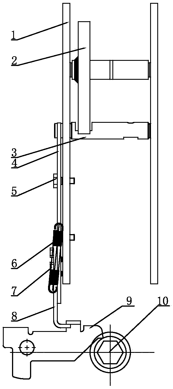
[0018] Now in conjunction with accompanying drawing, the present invention will be further described. Such as Figure 1 ~ Figure 4 As shown, the chassis car rotating shaft 10 and the chassis car lock plate 9 of the chassis car interlocking device are installed on the chassis car support in parallel, and the chassis car lock plate at the opposite end of the chassis car lock plate and the chassis car rotating shaft is provided with a hook, and the chassis car lock plate The splint 1 at the limit hook is equipped with an interlocking plate; the interlocking plate includes the first interlocking plate 4 and the second interlocking plate 8, that is, the first interlocking plate and the second interlocking plate form the interlocking plate assembly, and the second The first interlocking plate and the second interlocking plate are connected as a whole through the second fixing screw 7, and the second interlocking plate at the second fixing screw is provided with an adjustment hole. ...


PUM


Abstract

The invention relates to an operating mechanism chassis truck interlocking device and an interlocking method thereof. A chassis truck rotating shaft of the chassis truck locking device and a chassis truck locking plate are installed on a chassis truck support in a parallel mode, and a limiting hook of the chassis truck locking plate is provided with an interlocking plate. A switching-on pinch plate is installed on a pinch plate shaft between clamping plates, and one end of the switching-on pinch plate abuts against the a switching-on half shaft between the clamping plates. The operating mechanism chassis truck locking device is characterized in that a half-circular half shaft end at one end of the switching-on half shaft extends out of the clamping plate on one side, the straight edge of the half-circular half shaft end of the switching-on half shaft abuts against the side edge of one end of the interlocking plate, the interlocking plate is installed on the clamping plates through a first fixing screw, parts where the first fixing screw is located of the interlocking plate are provided with sliding holes, the limiting hook of the chassis truck locking plate and an interlocking hook at the other end of the interlocking plate are buckled, and the chassis truck locking plate is driven by the rotation of the chassis truck rotating shaft to rotate. The chassis truck rotating shaft is shaken, the chassis truck locking plate is lifted, and an operating mechanism cannot be switched on. When the chassis truck rotating shaft is shaken in place, the chassis truck locking plate is pressed by the chassis truck rotating shaft, and the operating mechanism can be switched on.

Description

technical field [0001] The invention relates to an operating mechanism chassis vehicle of a high-voltage switch electrical appliance, in particular to an interlocking device and an interlocking method for the operating mechanism chassis vehicle. Background technique [0002] The chassis of the operating mechanism of the high-voltage switch is used to push and withdraw the circuit breaker, and is used as an auxiliary operation for on-off of the circuit breaker and the busbar. The chassis structure of this type of operating mechanism is disclosed in the Chinese patent literature with the application number 200920190382.3, the date of authorization announcement is 2010.05.26, and the name of the utility model is "indoor high-voltage vacuum circuit breaker". The high-voltage vacuum circuit breaker includes a primary conductive part, a box And operating mechanism, chassis car, the primary conductive part is composed of vacuum interrupter, vacuum pole, static contact and moving co...

Claims


Application Information

Patent Timeline
Patent Type & Authority Patents(China)
IPC IPC(8): H02B11/133
Inventor 胡光福应岳君
Owner 宁波剑润机电有限公司
Learn More