Check patentability & draft patents in minutes with Patsnap Eureka AI!

Video image encoding and decoding device and method and transmission system and method

A technology of video image and encoding device, which is applied in the field of communication, can solve the problems of high cost and low efficiency, and achieve the effects of saving cost, improving encoding efficiency, and improving decoding efficiency

Active Publication Date: 2014-04-30
GUANGDONG VTRON TECH CO LTD
View PDF10 Cites 8 Cited by
  • Summary
  • Abstract
  • Description
  • Claims
  • Application Information

AI Technical Summary

Problems solved by technology

[0005] Based on this, it is necessary to provide a video image encoding and decoding device and its method, a transmission system and its method for the problems of high cost and low efficiency when encoding and decoding video images

Method used


Image

  • Video image encoding and decoding device and method and transmission system and method
  • Video image encoding and decoding device and method and transmission system and method
  • Video image encoding and decoding device and method and transmission system and method

Examples


Embodiment Construction

[0050] Various embodiments of the video image encoding and decoding device and method thereof, transmission system and method thereof of the present invention will be described in detail below.

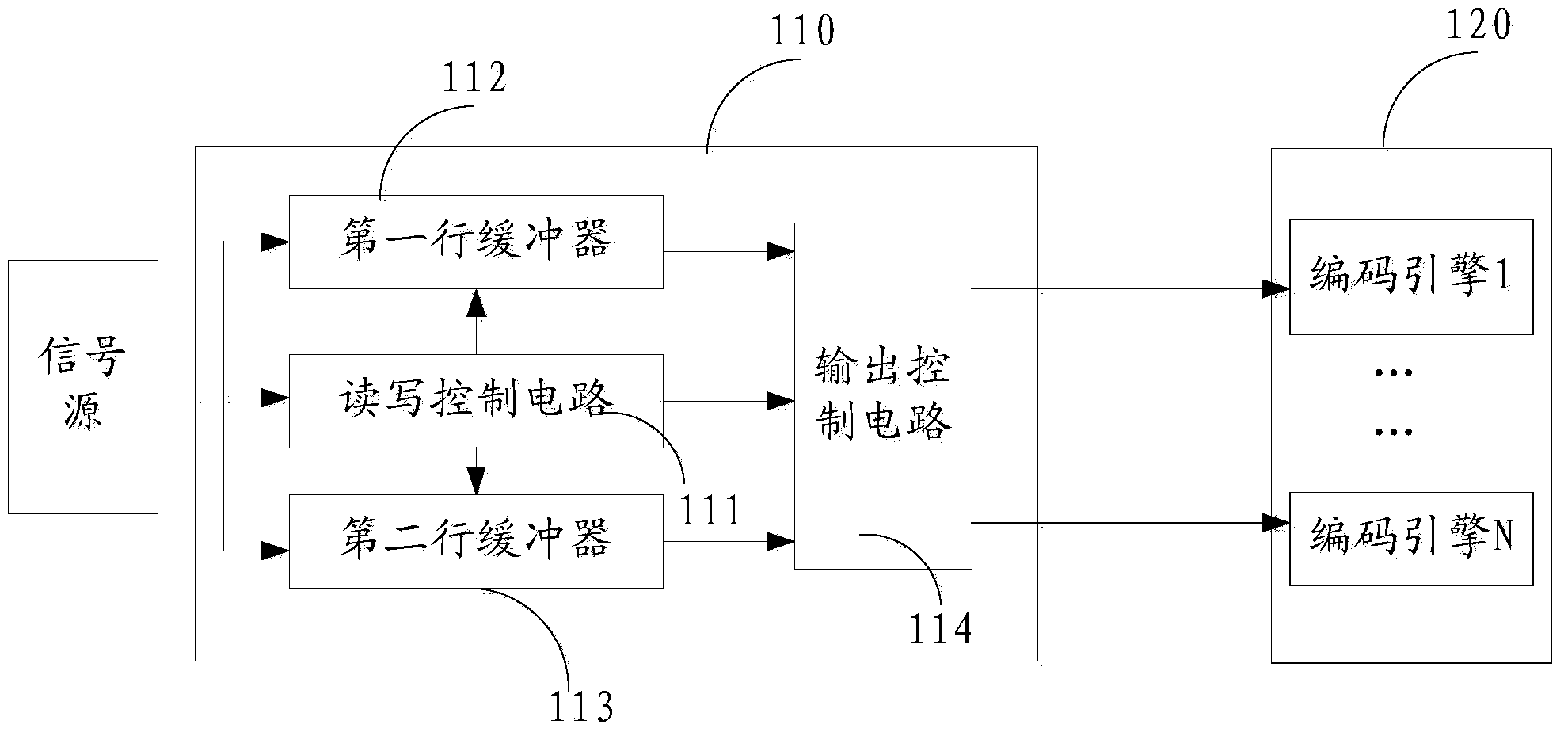
[0051] Such as figure 1 As shown, it is a schematic structural diagram of an embodiment of the video image encoding device of the present invention, including: a segmentation module 110 and an encoding module 120, and the segmentation module includes a read-write control circuit 111, a first line buffer 112, a second line buffer 113, an output The control circuit 114, the encoding module includes a plurality of encoding engines, the number of encoding engines is the same as the multiple value, wherein the multiple value is the multiple of the resolution of the video image and the resolution of the encoding module. The multiplier value may be determined according to the resolution of the video image and the resolution multiple of the encoder. For example, here the multiple value is as...


PUM


Abstract

The invention discloses a video image encoding and decoding device and method thereof and a transmission system and method. The transmission system comprises a segmenting module, an encoding module, a decoding module and a splicing module. The segmenting module comprises a read-write control circuit, a first-line buffer, a second-line buffer and an output control circuit. The encoding module comprises a plurality of encoding engines. The decoding module comprises a plurality of decoding engines. The number of the decoding engine and the number of the encoding engines are the same as multiple values. The multiple values are the multiples of a video image resolution ratio and an encoding module resolution ratio. The first-line buffer, the second-line buffer and the read-write control circuit are respectively connected with a signal source. The read-write control circuit is respectively connected with the first-line buffer, the second-line buffer and the output control circuit. The output control circuit is respectively connected with the first-line buffer, the second-line buffer and the encoding module. The encoding module, the decoding module and the splicing module are sequentially connected. Therefore, video images are encoded, decoded and transmitted, the cost is low, and efficiency is high.

Description

technical field [0001] The present invention relates to the field of communication technology, in particular to a video image codec device and its method, a transmission system and its method. Background technique [0002] Existing video codec systems generally include a signal source, an encoding module, a decoding module, and a display connected in sequence, and the encoding module and the decoding module are connected through a network. The video signal source outputs a video image, and the encoding module receives the image signal with full resolution and encodes it. The coded video code stream is transmitted to the decoder through the network, and then output to the display after being decoded. Existing video codec systems are suitable for systems with a maximum resolution of 1080p (ie 1920*1080). [0003] With the development of technology, the resolution of video images is getting larger and larger, especially exceeding high-definition images (typical resolution is ...

Claims


Application Information

Patent Timeline
IPC IPC(8): H04N19/129H04N19/132H04N19/40H04N19/46
Inventor 周小鹏罗虎
Owner GUANGDONG VTRON TECH CO LTD
Features
  • R&D
  • Intellectual Property
  • Life Sciences
  • Materials
  • Tech Scout
  • Unparalleled Data Quality
  • Higher Quality Content
  • 60% Fewer Hallucinations
Learn More