
Gas turbine engine compressor arrangement

A gas turbine and engine technology, applied in gas turbine devices, machines/engines, jet propulsion devices, etc., can solve problems such as reduced compression efficiency and complicated pipeline connections

Active Publication Date: 2014-04-30
UNITED TECH CORP
View PDF6 Cites 3 Cited by
  • Summary
  • Abstract
  • Description
  • Claims
  • Application Information

AI Technical Summary

Problems solved by technology

[0007] Disadvantageously, relative motion between parts of the compressor can alter the rotor tips and other clearances within the compressor, which can reduce compression efficiency
Also, using an inlet box to support the compressor can complicate access to some piping connections near the inlet box

Method used


Image

  • Gas turbine engine compressor arrangement
  • Gas turbine engine compressor arrangement
  • Gas turbine engine compressor arrangement

Examples


Embodiment Construction

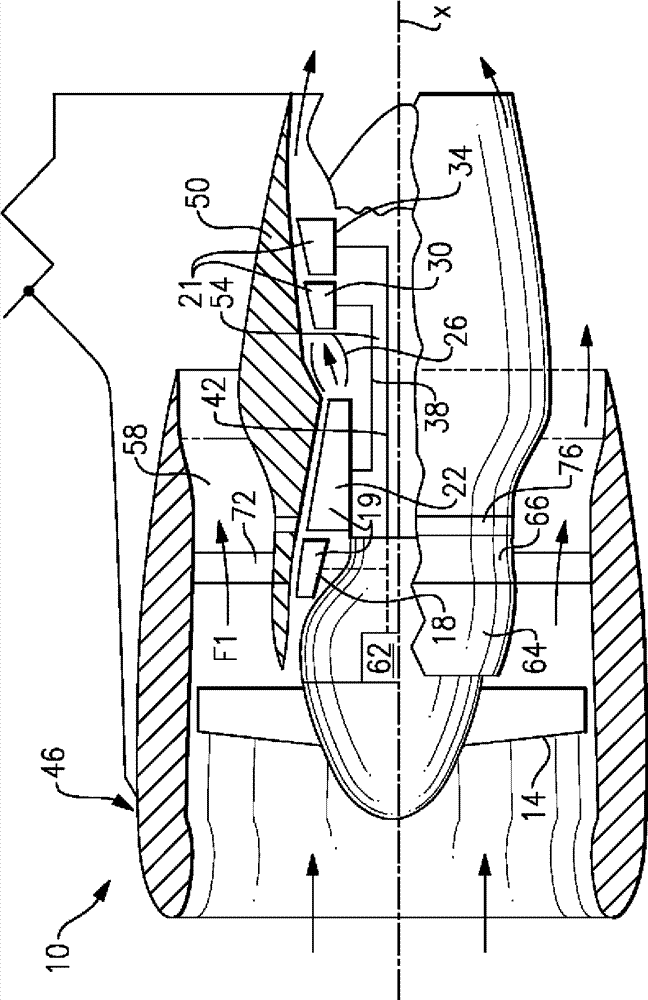
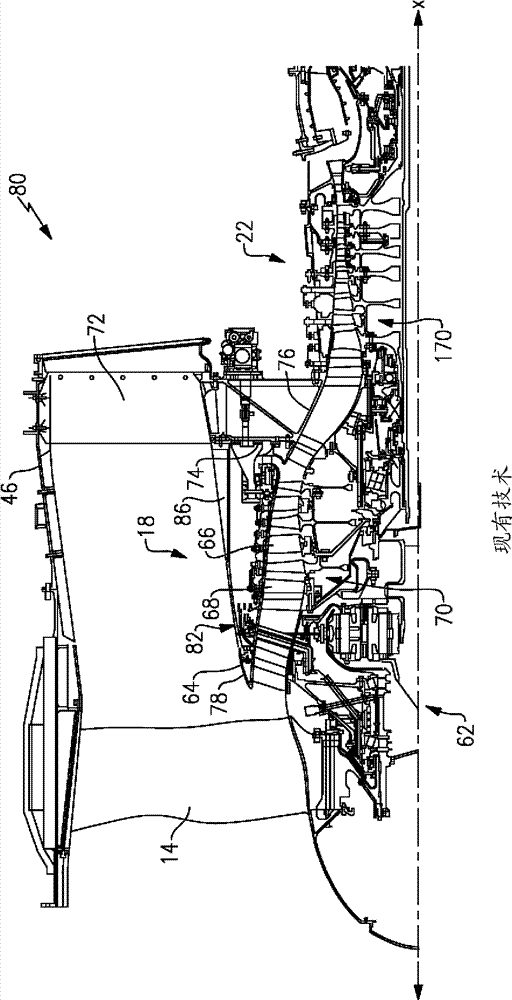
[0037] figure 1 An example gas turbine engine 10 is schematically shown, including (in series flow communication) a fan section 14 containing the compression of a low pressure (or first) compressor section 18 and a high pressure (or second) compressor section 22 . Engine section 19 , combustor 26 , and turbine section 21 including high pressure (or second) turbine section 30 and low pressure (or first) turbine section 34 . The gas turbine engine 10 is arranged circumferentially about an engine centerline X. As shown in FIG. During operation, air is drawn into gas turbine engine 10 through fan section 14 , pressurized by compressors 18 , 22 , mixed with fuel, and combusted in combustor 26 . Hot combustion gases generated within the combustor 26 flow through high and low pressure turbines 30, 34, extracting energy from the hot combustion gases. As used herein, a "high pressure" compressor or turbine is subject to a higher pressure than a corresponding "low pressure" compressor...


PUM


Abstract

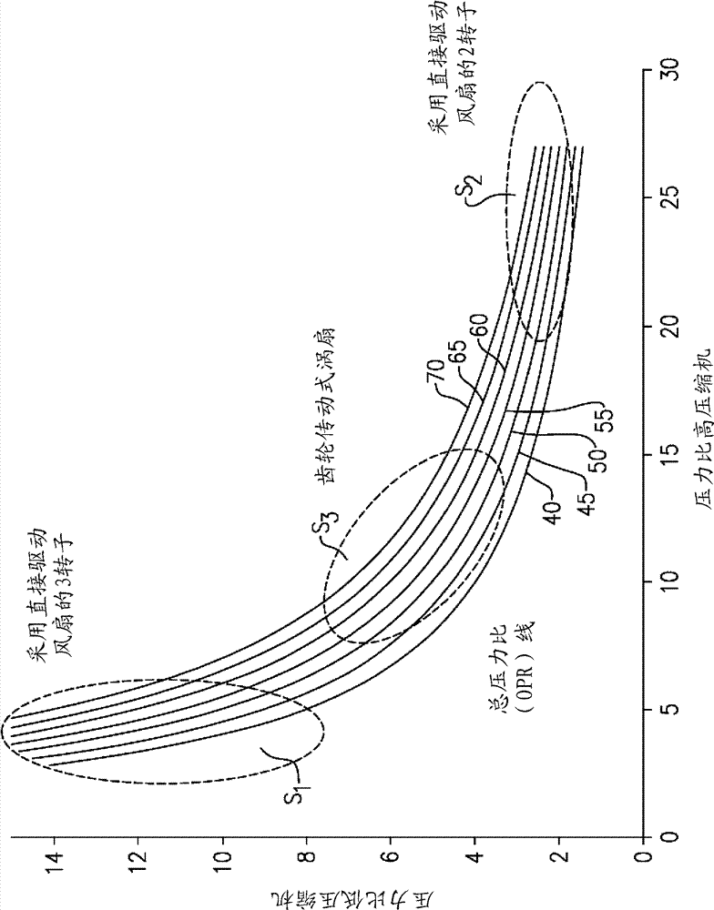
A gas turbine engine includes a fan section, a gear arrangement configured to drive the fan section, a compressor section and a turbine section. The compressor section includes a low pressure compressor section and a high pressure compressor section. The turbine section is configured to drive compressor section and the gear arrangement. An overall pressure ratio, which is provided by a combination of a pressure ratio across said low pressure compressor section and a pressure ratio across said high pressure compressor section, is greater than about 35. The pressure ratio across the low pressure compressor section is between about 3 and about 8 whereas the pressure ratio across the high pressure compressor section is between about 7 and about 15.

Description

[0001] Cross References Related to Application [0002] This application claims priority to U.S. Provisional Application 61 / 604,646, filed February 29, 2012, and to U.S. Patent Application No. 13 / 646, filed December 27, 2011, entitled "Gas Turbine Engine Compressor Apparatus" 337,354, U.S. Patent Application No. 13 / 337,354 is a continuation-in-part of U.S. Patent Application No. 13 / 294,492, filed November 11, 2011, entitled "Gas Turbine Compressor Case Mounting Apparatus," and US Patent Application No. 13 / 294492 is a continuation of US Patent Application No. 11 / 858,988, filed September 21, 2007, entitled "Gas Turbine Compressor Case Mounting Apparatus." technical field [0003] The present invention generally relates to a gas turbine engine. Background technique [0004] Gas turbine engines are known and typically include a compressor for compressing air and delivering it downstream into a combustion section. A fan moves air to the compressor. The compressed air is mixed ...

Claims


Application Information

Patent Timeline
IPC IPC(8): F01D1/04
CPCF02K3/06F02C3/107
Inventor K.L.哈塞尔J.B.斯陶巴赫B.D.梅丽G.L.苏丘C.M.戴
Owner UNITED TECH CORP
Learn More