Shifting-force support device

A technology for supporting devices, shifting forces, applied in the direction of transmission control, elements with teeth, belts/chains/gears, etc.

Active Publication Date: 2014-04-30
HOERBIGER AUTOMOTIVE KOMFORTSYST
View PDF8 Cites 0 Cited by
  • Summary
  • Abstract
  • Description
  • Claims
  • Application Information

AI Technical Summary

Problems solved by technology

[0007] The technical problem to be solved by the present invention is to remedy this disadvantage at least to a significant extent, that is, to at least significantly reduce the impact noise that occurs when shifting gears

Method used


Image

  • Shifting-force support device
  • Shifting-force support device
  • Shifting-force support device

Examples


Embodiment Construction

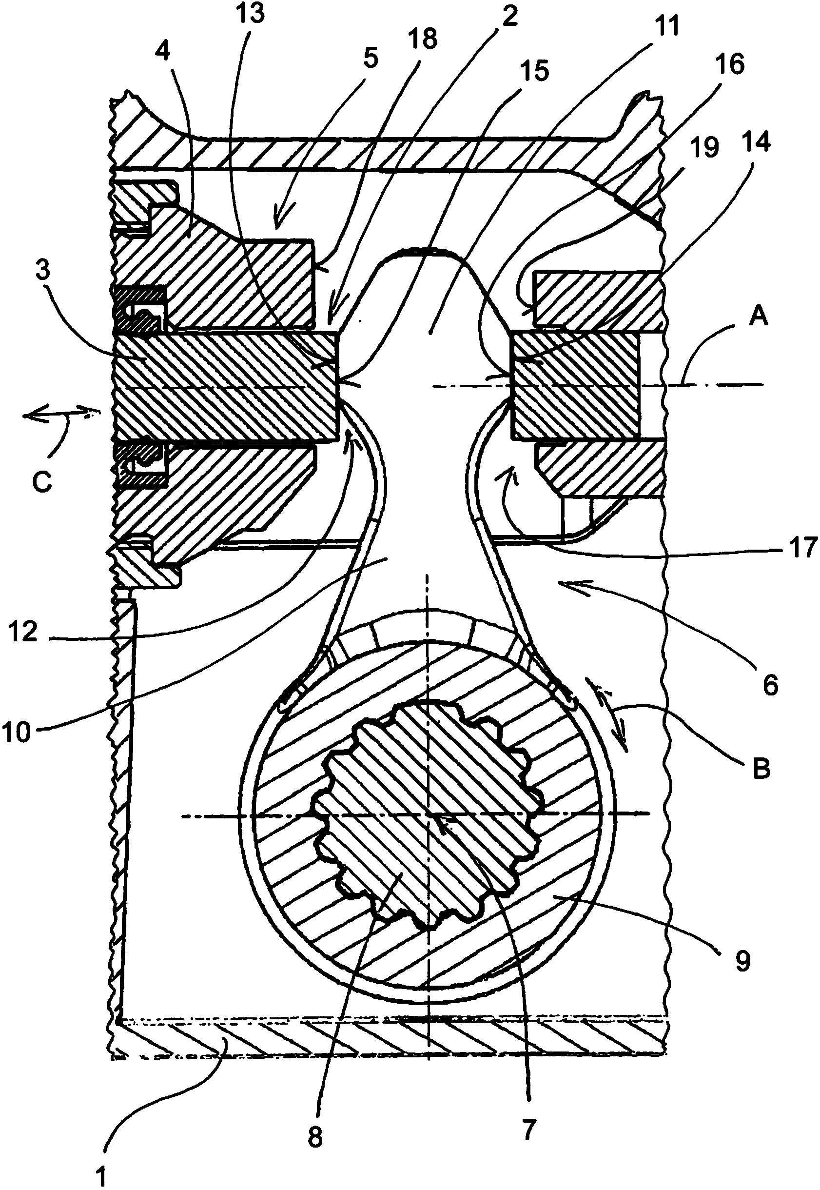
[0019] figure 1 The only areas of concern for conventional pneumatic shift force support devices for transmissions, which are mounted in the housing 1 and are movable relative to the housing 1 in the longitudinal direction A and which comprise sliding Block 2 , which is designed as a control rod 3 , which forms the input of the gearshift force support. The output of the shift force support is formed by the piston rod 4 , which surrounds the control rod 3 and is displaceable in the housing 1 relative to said control rod 3 in the longitudinal direction A and thus becomes the second slide 5 . .

[0020]A lever 6 is provided for actuating the control lever 3 , which is connected in a rotationally fixed manner to a shaft 8 (intermediate shaft) mounted rotatably about an axis 7 in the housing 1 , wherein for this purpose a hub 9 of the lever 6 and The shafts 8 engage one another in a form-fitting manner by means of corresponding contours. On the hub 9 of the lever 6 is formed an ...


PUM


Abstract

In a shifting-force support device for a manual transmission, in order to convert the rotational movement (B) of a shaft (8) into a linear movement (C) of a slider (2) or vice versa, a lever (6) which is connected to the shaft (8) is provided. Said lever has an arm (10) and a head (11) which engages in a recess (12) in the slider (2) and has two mutually opposite bearing surfaces (13, 14) interacting with mating surfaces (15, 16) of the recess (12) in the slider (2). In this case, in order to form two head sections (20, 21), the head (11) is slit between the two bearing surfaces (13, 14) in such a manner that the two bearing surfaces (13, 14) can be moved towards each other by a defined amount.

Description

technical field [0001] The invention relates to a pneumatic shift force support device for a transmission, in which a lever connected to the shaft is provided for converting the rotational movement of the shaft into a linear movement of the slide or vice versa, said lever having an arm and engaging in A head in the cavity of the slider, wherein the head has two mutually opposite abutment surfaces cooperating with the counter surfaces of the cavity of the slider. Background technique [0002] Shift force support devices for transmissions are widely used in commercial vehicles, for example with a structure known from DE 195 39 471 A1. Typically, a suitable mechanical coupling of the selector lever actuated by the vehicle driver to the first slider (input) of the shift force support device, the so-called control lever, is effected here. Between this control rod and the second slider, which is movable parallel to the control rod and forms the output of the shifting force suppor...

Claims


Application Information

Patent Timeline
IPC IPC(8): F16H61/30F16H63/30
CPCF16H2063/3089F16H61/30F16H2061/301F16H63/30
Inventor M.霍克特尔K.琼鲍尔H.克拉茨R.鲁克金格W.马克
Owner HOERBIGER AUTOMOTIVE KOMFORTSYST
Why Eureka
Try Eureka