
Solderable contact

A technology of contact parts and contact parts, which is applied in the direction of contact parts, welding/welding connections, parts of connection devices, etc., can solve the problems of contact spring deformation, deformation, etc., to reduce the risk of damage, avoid lateral distortion, and low defects The effect of rate and damage rate

Inactive Publication Date: 2014-04-30
AMPHENOL TUCHEL ELECTRONICS
View PDF7 Cites 0 Cited by
  • Summary
  • Abstract
  • Description
  • Claims
  • Application Information

AI Technical Summary

Problems solved by technology

[0009] In other words, the invention seeks to solve the technical problem of contact springs being subjected to residual deformations and deformations induced or occurring during assembly

Method used


Image

  • Solderable contact
  • Solderable contact
  • Solderable contact

Examples


Embodiment Construction

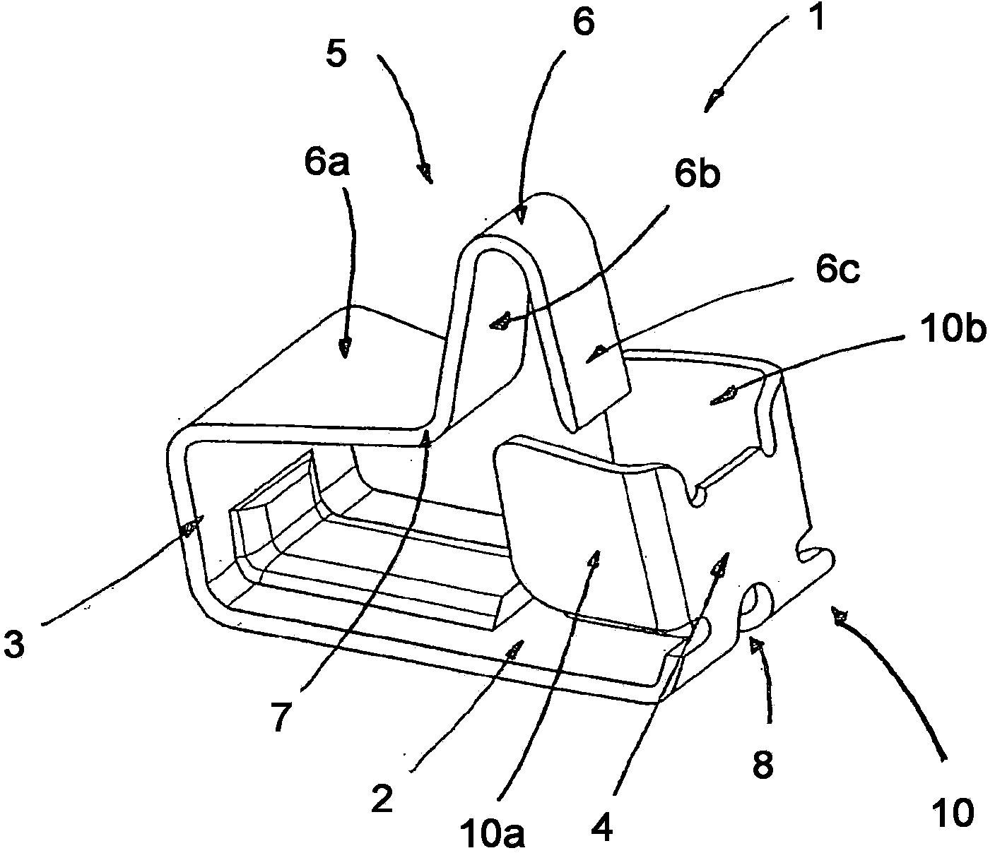
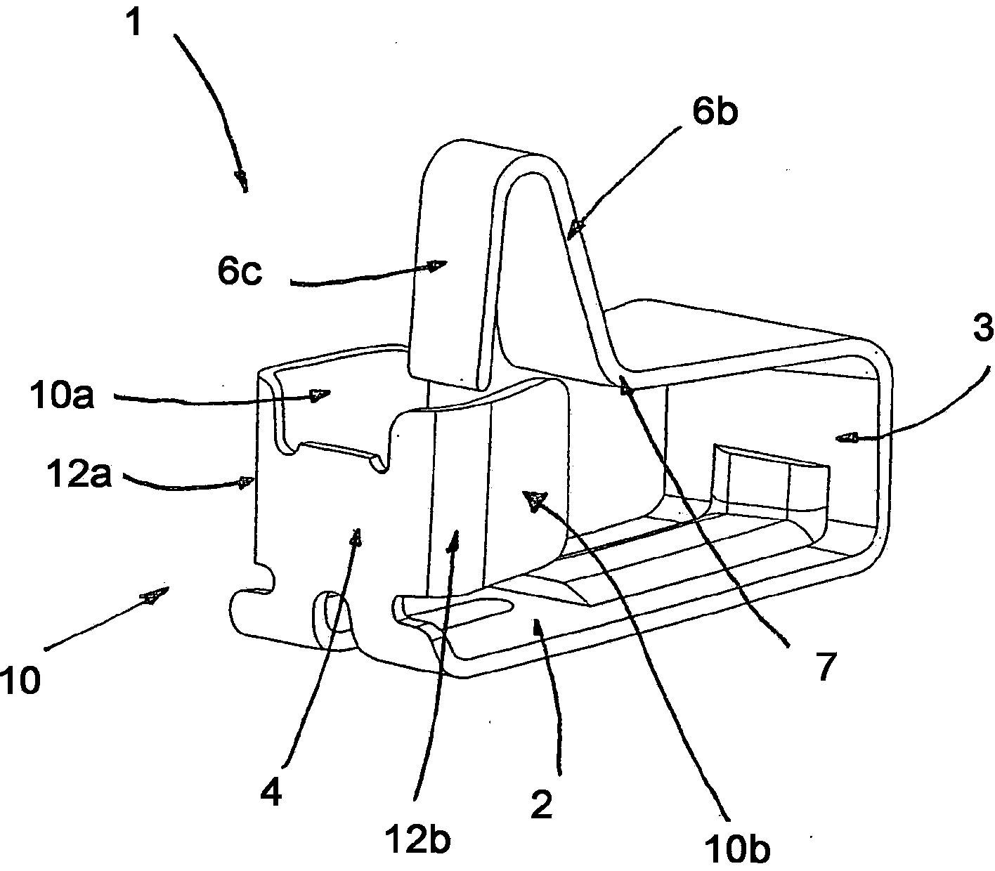
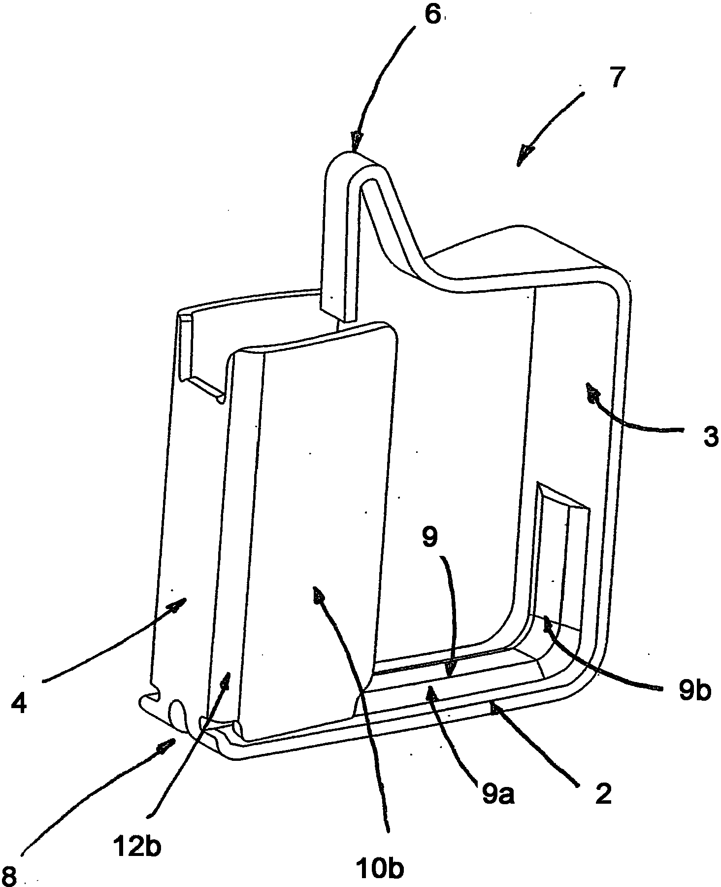
[0030] figure 1 with figure 2 A first exemplary embodiment of the invention is shown, more precisely a solder contact 1 or a spring terminal 1 .

[0031] The solder contact 1 is designed as an essentially U-shaped solder contact 1 which is formed from a base plate 2 with two legs 3 , 4 .

[0032] This U-shape is intended to represent the configuration of the base plate 2 and the two legs 3, 4, which are oriented at an angle of 90° relative to each other and in close proximity to each other.

[0033] Substrate (such as figure 1 shown in ) is designed as a substantially elongated or rectangular base plate 2 , on each longitudinal end of which a leg plate 3 and a leg plate 4 are arranged.

[0034] The leg plates 3 , 4 will hereinafter be referred to simply as legs 3 , 4 .

[0035] On the leg 3 is fixed an elastic arm 5 having a first elastic arm portion 6a extending substantially parallel to the base plate, which is adjacent to a second elastic arm portion 6b via a bend 7, ...


PUM


Abstract

The invention relates to a solderable contact formed by a substantially U-shaped contact part consisting of a base plate with two legs that are joined to the base plate. A spring arm which is arranged on one leg extends in the direction of the leg opposite said leg. The opposite leg has two lateral wings which are form-fittingly connected to the leg by means of connecting sections.

Description

technical field [0001] The invention relates to a soldering contact / soldering contact according to the preamble of claim 1 . [0002] The invention therefore relates to a springable soldering contact for soldering to a component carrier, in particular to a printed circuit board. Background technique [0003] Various solder contact embodiments are known from the prior art. [0004] DE60220266T2 discloses a spring contact consisting of a (metal) sheet of elastic material and comprising a base strip and a contact strip, wherein the contact strip is laterally spaced from the base strip and forms a gap therebetween And an elastic bending region is provided which connects the end of the base strip to the end of the contact strip, wherein the base strip and the contact strip extend in the longitudinal direction and the elastic bending region is elastically preloaded. [0005] Solder contacts are generally soldered to a printed circuit board or to a touch screen or a contact posit...

Claims


Application Information

Patent Timeline
Patent Type & Authority Applications(China)
IPC IPC(8): H01R4/02H01R13/24
CPCH01R13/2442H01R4/02H01R12/57H01R13/17
Inventor M·诺里奇A·拉克劳斯基
Owner AMPHENOL TUCHEL ELECTRONICS
Learn More