Separated bandwidth

A technology of isolation belt and surface layer, which is applied in the direction of insulation layer, floor, covering/lining, etc., can solve the problems of material consumption and complex multi-layer structure of isolation belt, and achieve the effect of saving materials and reducing manufacturing costs

Inactive Publication Date: 2013-05-29
SANIKU
View PDF1 Cites 0 Cited by
  • Summary
  • Abstract
  • Description
  • Claims
  • Application Information

AI Technical Summary

Problems solved by technology

[0004] The known separators also involve the disadvantage that the multilayer structure of the separators is complex to produce and also consumes material

Method used


Image

  • Separated bandwidth
  • Separated bandwidth
  • Separated bandwidth

Examples


Embodiment Construction

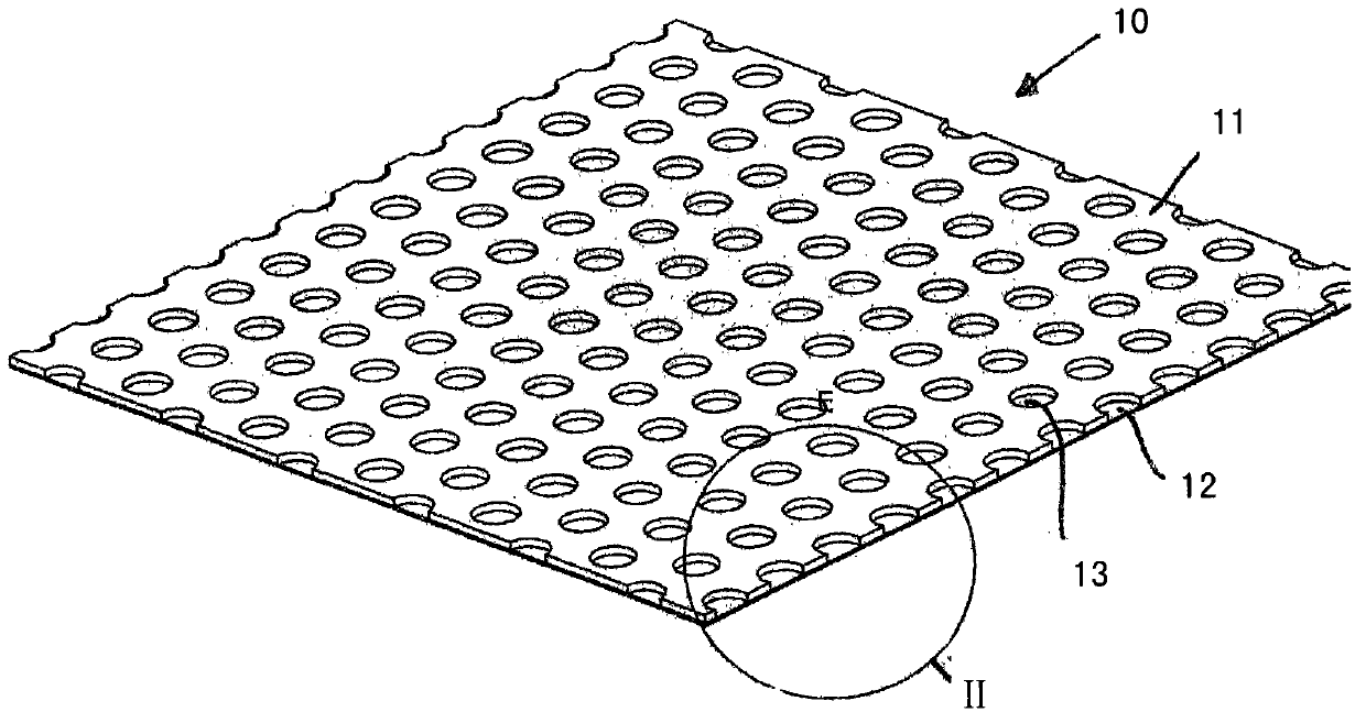
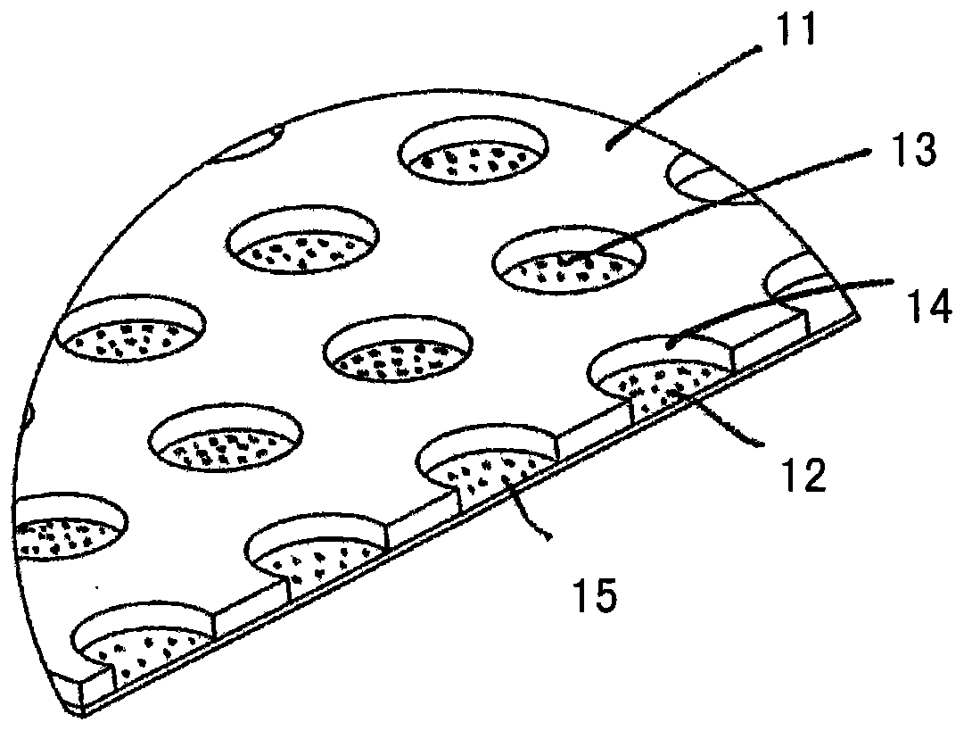
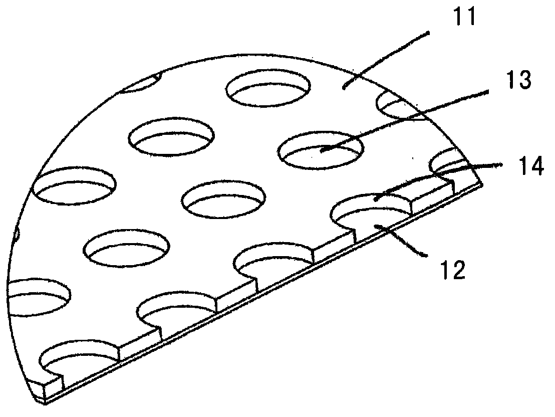
[0019] The insulating strip 10 shown in the drawings consists of two interconnected layers, to be precise, a foam layer 11 formed by foaming a waterproof and dimensionally stable foam material with small openings and a foam layer 11 according to the shown attachment. Figure laying the bottom layer 12 on its bottom surface. After the foam layer 11 has been produced, the base layer 12 can then be connected, preferably glued, to the foam layer 11 .

[0020] In the exemplary embodiment shown, perforations 13 are distributed evenly along the surface of the foam layer 11 and extend from the exposed surface of the foam layer 11 as far as the base layer 12 lying thereon. Each individual perforation 12 thus forms a surrounding wall 14 which consists of the foam material of the foam material layer 11 with small openings.

[0021] To produce the foam layer 11 it is expedient to extrude the respectively used foam. In this case, the perforations 13 can be formed directly during the extru...


PUM


Abstract

Provided is a separated bandwidth used for laying on beading members on a ceramic layer, a rocky surface or a similar surface layer of a lower part structure and formed by a plurality of connected layers. The characteristics are that the separated bandwidth (10) formed by at least two layers (11,12) comprises a bottom film-like layer (12) to be laid on a lower part structure and a support layer (11) to be laid on and connected to the bottom layer (12) and used for laying on a surface layer, wherein the support layer (11) is formed by an open-pore, water resistant, non-deformable foam material having apertures (13), extending through the bottom layer (12), distributed over its surface.

Description

technical field [0001] The invention relates to an insulating strip, which is composed of a plurality of interconnected layers as a carrier for a ceramic, stone or similar surface to be laid on a substructure. Background technique [0002] In DE 202009001255U1 a separating strip having the aforementioned characteristics is described. The known insulating strip consists of a composite layer with a total of four layers. As a first layer to be laid on the substructure, for example in the form of a seamless floor (Estrich) or a wall plaster, a fiber mesh made of polypropylene fibers is provided, on which a waterproof layer is laid, preferably made of polyethylene film as the second layer. Spacer wires consisting of 100% polypropylene are again laid on the polyethylene film, and the spacer wires are in turn covered by a covering web of polypropylene filaments. Perforations extending from the surface to the spaced miscellaneous wires are opened on the covering fiber net. [00...

Claims


Application Information

Patent Timeline
Patent Type & Authority Applications(China)
IPC IPC(8): E04F15/18
CPCE04F15/183E04F15/186E04F15/182E04F15/185B32B3/266E04F13/072
Inventor H·杜萨尔
Owner SANIKU
Why Eureka
Try Eureka